Separating device

a separation device and separating member technology, applied in the direction of electrographic process equipment, instruments, optics, etc., can solve the problems of shortening the life of the photoreceptor drum, unable to obtain the required paper separation performance, and inability to extend the maintenance cycle of the image forming apparatus, so as to reduce the rotational moment, reduce the abrasion of the surface, and effectively prolong the life of the separating member and the photoreceptor drum

Active Publication Date: 2012-10-11
SHARP KK
View PDF4 Cites 2 Cited by
  • Summary
  • Abstract
  • Description
  • Claims
  • Application Information

AI Technical Summary

Benefits of technology

[0018]The present invention has been devised in view of the above-described circumstances, it is therefore an object of the present invention to provide a separating device that can prevent the front end of the separating member that abuts the photoreceptor drum from floating and can lengthen the lives of the separating member and photoreceptor drum by suppressing abrasion of the photoreceptor drum surface.
[0020]According to one aspect of the present invention, a separating device for separating a sheet medium being stuck on an outer peripheral surface of a photoreceptor drum, the separating device includes: a separating member that abuts the sheet medium being conveyed along an outer peripheral surface of the photoreceptor drum and separates the sheet medium from the photoreceptor drum; a separating member driver that causes the separating member to abut on and separate from the photoreceptor drum and changes a position of a rotational supporting point of the separating member, and wherein the separating member has a tapered, wedge-shaped front end that abuts the outer peripheral surface of the photoreceptor drum, the front end is rotatably supported in such a manner as to rotate about the rotational supporting point that is disposed on a line parallel to an axis of the photoreceptor drum, and the separating member driver changes the position of the rotational supporting point so that, as larger reactive force that occurs at a contact point where the front end comes in contact with the photoreceptor drum on the outer peripheral surface of the photoreceptor drum, so as to decrease rotational moment of the reactive force on the rotational supporting point of the separating member is lower.
[0025]With the aspect of the present invention, a separating device for separating a sheet medium being stuck on an outer peripheral surface of a photoreceptor drum, the separating device includes: a separating member that abuts the sheet medium being conveyed along an outer peripheral surface of the photoreceptor drum and separates the sheet medium from the photoreceptor drum; a separating member driver that causes the separating member to abut on and separate from the photoreceptor drum and changes a position of a rotational supporting point of the separating member, and wherein the separating member has a tapered, wedge-shaped front end that abuts the outer peripheral surface of the photoreceptor drum, the front end is rotatably supported in such a manner as to rotate about the rotational supporting point that is disposed on a line parallel to an axis of the photoreceptor drum, and the separating member driver changes the position of the rotational supporting point so that, as larger reactive force that occurs at a contact point where the front end comes in contact with the photoreceptor drum on the outer peripheral surface of the photoreceptor drum, so as to decrease rotational moment of the reactive force on the rotational supporting point of the separating member is lower, so that this configuration can prevent the front end of the separating member that abuts the photoreceptor drum from floating and secure stable separating performance of the separating member, and also is markedly effective to lengthen the lives of the separating member and the photoreceptor drum by suppressing abrasion of the photoreceptor drum surface.
[0026]With the aspect of the present invention, the separation member driver changes the position of the rotational supporting point of the separating member from an outer side toward an interior side with respect to a tangent line at the contact point, which makes it possible to decrease the rotational moment that occurs at the separating member by moving the position of the rotational supporting point of the separating member from the outer side to the inner side with respect to the tangent line at the contact point, and hence reduce abrasion of the surfaces of the separating member and the photoreceptor drum. As a result, this configuration can markedly, effectively lengthen the part lives of the separating member and the photoreceptor drum.
[0027]With the aspect of the present invention, the separating member driver changes the position of the rotational supporting point of the separating member as an amount of abrasion at the front end of the separating member increases. Accordingly, this configuration makes it possible to secure stable separating performance of the separating member and also suppress abrasion of the surfaces of the separating member and the photoreceptor drum. As a result, this configuration can markedly, effectively in lengthen the part lives of the separating member and the photoreceptor drum.
[0028]With the aspect of the present invention, the separating member driver changes the position of the rotational supporting point of the separating member, in a direction along the plane that is formed by a rotational axis of the photoreceptor drum and a rotational axis of a transfer roller or in such a direction as to increase an inclined angle formed with respect to the tangent line at the contact point as a reference, so that it is hence possible to secure stable separating performance of the separating member, and suppress abrasion of the surfaces of the separating member and the photoreceptor drum. As a result, this configuration can markedly, effectively lengthen the part lives of the separating member and the photoreceptor drum.

Problems solved by technology

If this wearing progresses rapidly, it is impossible to extend the maintenance cycle of the image forming apparatus since the life of paper separation claw 131 is estimated to be short.
Further, when a material having an extremely high wear resistance is used in order to suppress paper separation claw 131 from being worn, this scratches or damages photoreceptor drum 3, causing the problem of shortening the life of photoreceptor drum 103.
Further, as front end 131a of paper separation claw 131 is worn down, the front end 131a of paper separation claw 131 floats from the photoreceptor drum 103 surface due to a slight eccentricity of photoreceptor drum 3 as the photoreceptor rotates, causing the problem that the required paper separating performance cannot be obtained.
However, since, in the configuration shown in patent document 1, the position of the rotational axis that enables the claw-like separating member to pivot is fixed, the front end part of the claw-like separating member is abraded so that the contact area of the claw-like separating member with the photoreceptor drum becomes greater, causing the problem that the front end part (the tip of the contact surface) of the claw-like separating member floats due to eccentricity of the photoreceptor drum, resulting in separation failure.
Further, as the contact area between the claw-like separating member and the photoreceptor drum becomes greater, the risk of foreign substances building up between the claw-like separating member and the photoreceptor drum becomes higher, giving rise to a problem that the foreign substances accelerate abrasion of the photoreceptor drum.
Further, no consideration is given about the influence of the reactive force the separating member receives from the photoreceptor drum and the rotational moment generated in the separating member, resulting from the enlargement and complexity of the arrangement around the separating member, hence there occurs the problem that the front end of the separating member abutting against the photoreceptor drum floats.

Method used


Image

  • Separating device
  • Separating device
  • Separating device

Examples


Embodiment Construction

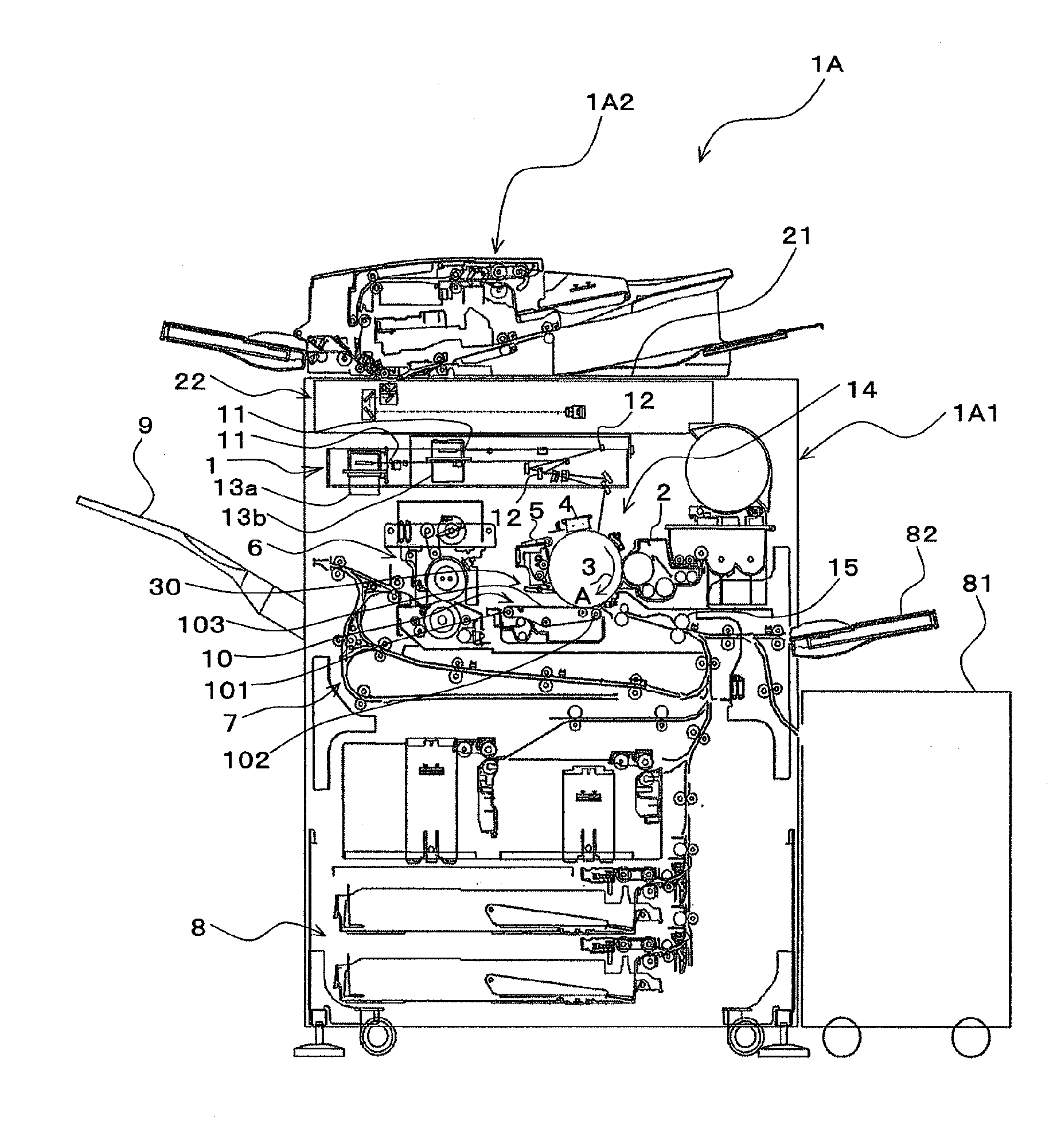
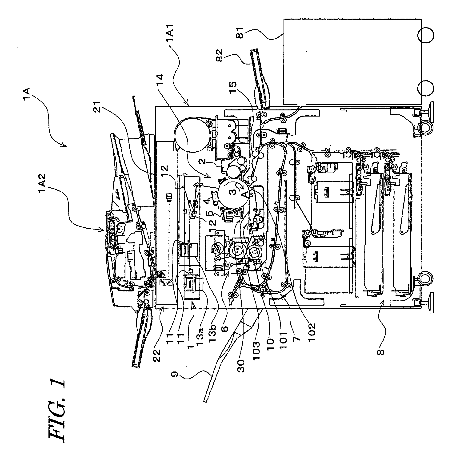
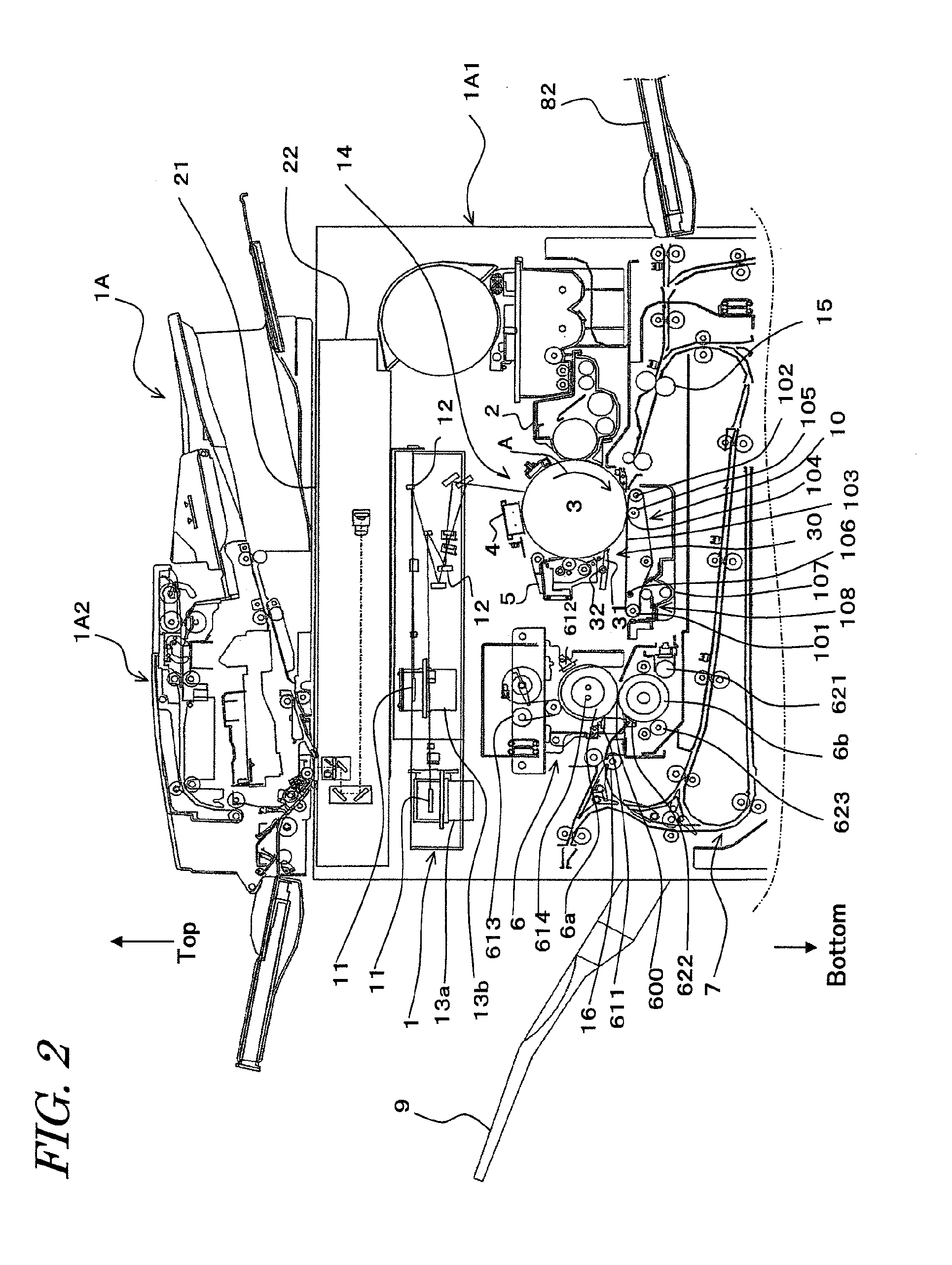
[0037]Referring next to the drawings, a separating device 30 according to the present embodiment will be described in detail. FIG. 1 is an illustrative diagram showing the overall configuration of an image forming apparatus including a separating device according to the present embodiment. FIG. 2 is a partial detailed diagram showing the configuration of the machine body of the image forming apparatus.

[0038]Separating device 30 according to the present embodiment includes a separation claw (separating member) 31 that abuts the paper (sheet medium) conveyed along the outer peripheral surface of a photoreceptor drum 3 to separate the paper from photoreceptor drum 3; and a separation claw driving mechanism (separating member driver) 32 for abutting and releasing separation claw 31 to and from photoreceptor drum 3, and is configured to separate the paper stuck to the outer peripheral surface of photoreceptor drum 3.

[0039]Separation claw 31 is constructed so that the separating part (fro...


PUM


Abstract

The separating part of the separating device receives a reactive force that occurs on the outer peripheral surface of the photoreceptor drum, at the contact point where the separating part and the photoreceptor drum are in contact.The separating device controller changes the position of the rotational supporting point so as to decrease the rotational moment M of the reactive force at the rotational supporting point of the separating device, in accordance with increase of the reactive force that occurs on the outer peripheral surface of the photoreceptor drum as the separating part is worn down.

Description

[0001]This Nonprovisional application claims priority under 35 U.S.C. §119(a) on Patent application No. 2011-086298 filed in Japan on 8 Apr. 2011, the entire contents of which are hereby incorporated by reference.BACKGROUND OF THE INVENTION[0002](1) Field of the Invention[0003]The present invention relates to a separating device, in particular, relating to a separating device for separating a sheet-like medium stuck on the outer periphery of a photoreceptor drum by means of a separating member.[0004](2) Description of the Prior Art[0005]Conventionally, in image forming apparatus using electrophotography such as a facsimile machines, printers and the like, image output is carried out by the steps of electrifying a rotationally driven photoreceptor drum by a charger, forming an electrostatic latent image on the photoreceptor drum by irradiation with light in accordance with image information, forming a toner image by applying toner to this electrostatic latent image by means of a deve...

Claims


Application Information

Patent Timeline
Patent Type & Authority Applications(United States)
IPC IPC(8): G03G15/00
CPCG03G15/6532G03G2215/004G03G2215/00573G03G15/657
Inventor YAMAUCHI, HIROKAZUMASUDA, JUNYA
Owner SHARP KK
Why Eureka
Try Eureka