Liquid Discharge Head and Printer

a liquid discharge head and printer technology, applied in printing and other directions, can solve the problems of difficult to secure a large length of the connecting channel, difficult to establish any resistance in the connecting channel, etc., and achieve the effect of stabilizing the flow of ink and lengthening the connecting channel

Active Publication Date: 2010-02-11
BROTHER KOGYO KK
View PDF2 Cites 2 Cited by
  • Summary
  • Abstract
  • Description
  • Claims
  • Application Information

AI Technical Summary

Benefits of technology

[0024]When the arrangement as described above is adopted, the connecting channels are arranged to extend in the direction intersecting with the extending direction of the common liquid chamber. Therefore, it is possible to miniaturize or small-size the ink-jet head. The portion of the connecting channel, which is disposed on the side of the communication with the common liquid chamber, is arranged at the outside with respect to the plan view contour line of the common ink chamber as viewed in a plan view. Therefore, it is possible to lengthen the connecting channel. Therefore, it is easy to establish a desired value of the channel resistance of the connecting channel. Thus, it is possible to stabilize the flow of the ink.
[0025]According to the present invention, as clarified from the foregoing explanation, it is possible to provide the liquid discharge head which contributes to the miniaturization or small sizing.

Problems solved by technology

However, in the case of the former ink-jet head, it is possible to realize the highly densified arrangement of the nozzles, while it is difficult to secure a large length of the connecting channel.
Therefore, it is difficult for the connecting channel to establish any channel resistance which is approximately the same as that of the nozzle.

Method used


Image

  • Liquid Discharge Head and Printer
  • Liquid Discharge Head and Printer
  • Liquid Discharge Head and Printer

Examples


first embodiment

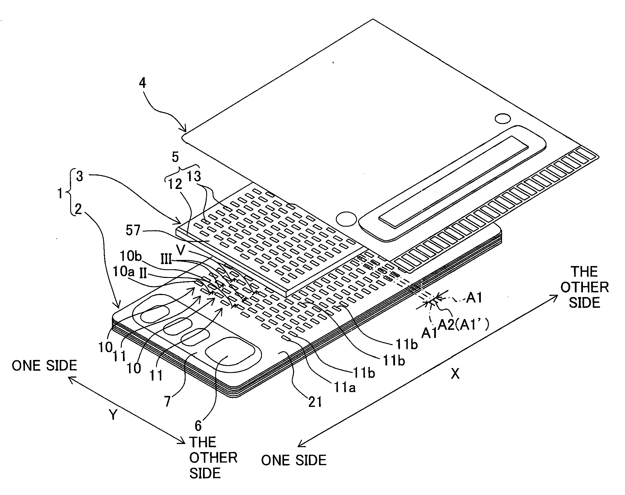
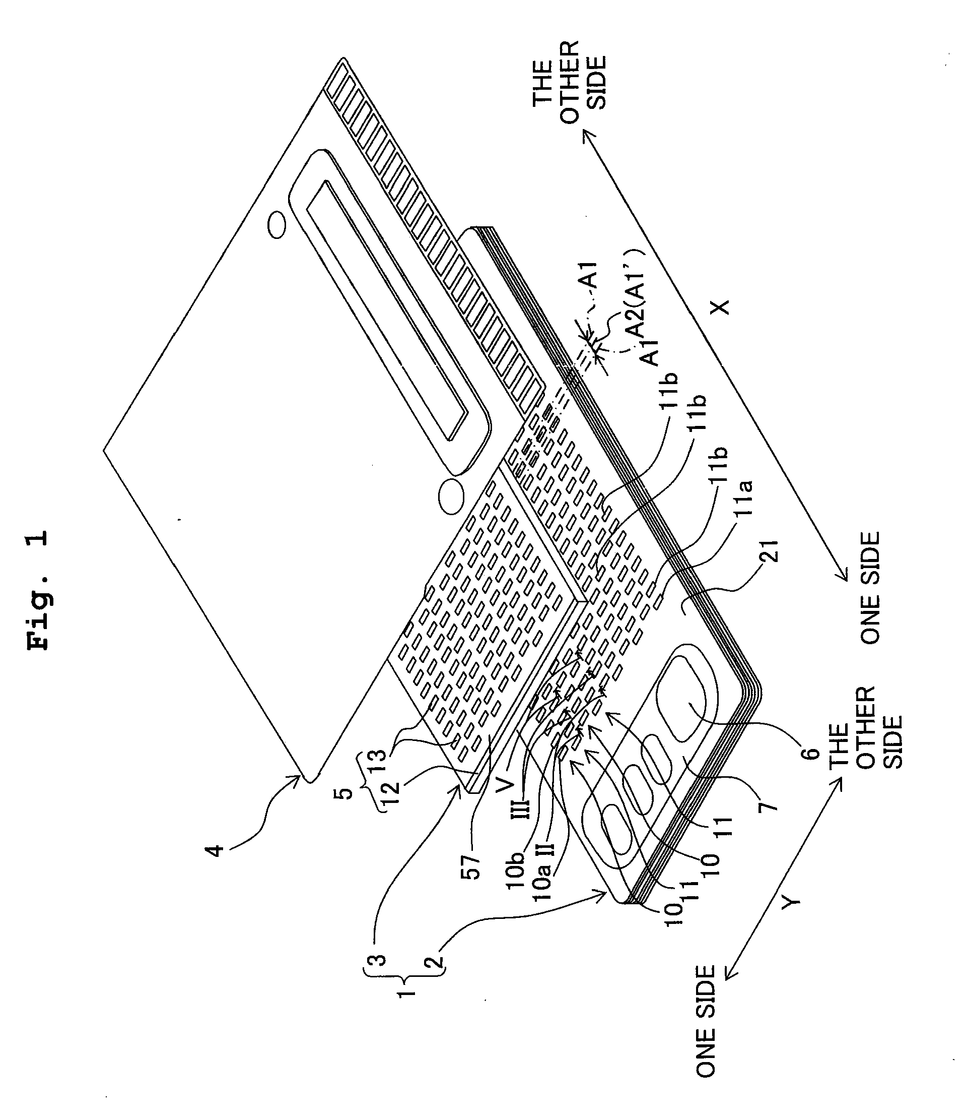
[0038]As shown in FIG. 1, the ink-jet head 1 is provided with a channel unit 2 which includes a plurality of stacked plates, and a piezoelectric type actuator 3 which is overlapped and adhered on the upper side with respect to the channel unit 2. Surface electrodes 5 are formed on the upper surface of the actuator 3. A flexible flat cable 4, which is provided to effect the electric connection to the external equipment, is overlapped and adhered on the upper side of the surface electrodes 5. Terminals (not shown) are exposed on the lower surface of the flexible flat cable 4. The terminals are electrically brought in conduction with the surface electrodes 5 of the actuator 3.

[0039]The channel unit 2 and the actuator 3 are formed to have substantially rectangular shapes as viewed in a plan view respectively. Conveniently, in the following description, the “X direction” is designated as the direction in which the long side of the rectangular shaped channel unit 2 (the actuator 3) extend...

second embodiment

[0088]FIG. 7 shows a vertical cross-sectional shape of a first connecting channel 138a connected to the pressure chamber 10a arranged on an odd-numbered row of the first pressure chamber array disposed on one side in the Y direction. FIG. 8 shows a vertical cross-sectional shape of a first connecting channel 138b connected to the pressure chamber 10b arranged on an even-numbered row of the first pressure chamber array disposed on one side in the Y direction. In this embodiment, first upstream channels 140a, 140b of the respective first connecting channels 138a, 138b are different from those of the first embodiment. The parts or components, which are constructed in the same manner as in the first embodiment, are designated by the same reference numerals, any detailed explanation of which will be hereinafter omitted.

[0089]As shown in FIG. 7, the first connecting channel 138a, which forms a part of an ink channel 130 of a channel unit 102, has a first upstream channel 140a. Further, th...

third embodiment

[0100]FIG. 9 shows a vertical cross-sectional shape of a first connecting channel 238a connected to the pressure chamber 10a for forming the first pressure chamber array 10 disposed on one side in the Y direction. In this embodiment, first and second connecting channels 240, 241 of the first connecting channel are different from those of the first embodiment. The parts or components, which are constructed in the same manner as in the first embodiment, are designated by the same reference numerals, any detailed explanation of which will be hereinafter omitted.

[0101]As shown in FIG. 9, the half etching processing is applied to the lower surface side of a second connecting channel plate 223. Accordingly, a first upstream channel 240a is formed as a groove which is open in the downward direction on the lower surface of the second connecting channel plate 223. The width (size or dimension in the X direction) of the first upstream channel 240a is equal to the width of the first upstream c...


PUM


Abstract

A plurality of pressure chambers are arranged in two arrays in a direction intersecting an extending direction of a common liquid chamber. First pressure chambers of one array and second pressure chambers of the other array are disposed in a staggered arrangement. First and second connecting channels extend, in the intersection direction, from the first and second pressure chambers through areas located between the second and first pressure chambers up to areas outside the common liquid chamber to make communication with the common liquid chamber, respectively. The first and second connecting channels are arranged alternately in relation to the extending direction. Accordingly, both of the insurance of the length of the connecting channel and the small sizing of a head are satisfied.

Description

CROSS REFERENCE TO RELATED APPLICATION[0001]The present application claims priority from Japanese Patent Application No. 2008-201869, filed on Aug. 5, 2008, the disclosure of which is incorporated herein by reference in its entirety.BACKGROUND OF THE INVENTION[0002]1. Field of the Invention[0003]The present invention relates to a liquid discharge head having a plurality of nozzles for jetting a liquid, including, for example, an ink-jet head to be carried, for example, on an ink-jet printer. The present invention relates to a printer such as an ink-jet printer.[0004]2. Description of the Related Art[0005]The ink-jet head is provided with a channel unit which has ink channels communicated with nozzles, and an actuator which is stacked on the channel unit. The ink channel has a common ink chamber to which an ink is supplied from an ink supply source, a plurality of pressure chambers which are provided corresponding to the plurality of nozzles, and a plurality of connecting channels wh...

Claims


Application Information

Patent Timeline
Patent Type & Authority Applications(United States)
IPC IPC(8): B41J2/14B41J2/175
CPCB41J2/14209B41J2002/14217B41J2002/14459B41J2002/14306B41J2002/14419B41J2002/14225
Inventor ITO, ATSUSHI
Owner BROTHER KOGYO KK
Why Eureka
Try Eureka