Automated surgical illumination system

a surgical lighting and automatic technology, applied in the field of surgical lighting systems, can solve the problems of not being able to move the lights, introducing the complication of voice recognition, and suffering from similar downsides

Active Publication Date: 2012-10-11
KIM GABRIEL MIN +1
View PDF2 Cites 19 Cited by
  • Summary
  • Abstract
  • Description
  • Claims
  • Application Information

AI Technical Summary

Benefits of technology

[0006]The present invention provides illumination for a surgical procedure. Using an optical tracking system, the illumination is made to au

Problems solved by technology

The solution by Luntsford eliminates the need for surgical personnel to manually move surgical lamps by allowing them to remotely control the lamps, but does not totally eliminate the need to have surgical personnel to initiate such movements, and is therefore only semi-automatic.
The solution by Borders suffers from a similar downside, as a user is required to control the disclosed

Method used


Image

  • Automated surgical illumination system
  • Automated surgical illumination system
  • Automated surgical illumination system

Examples


Embodiment Construction

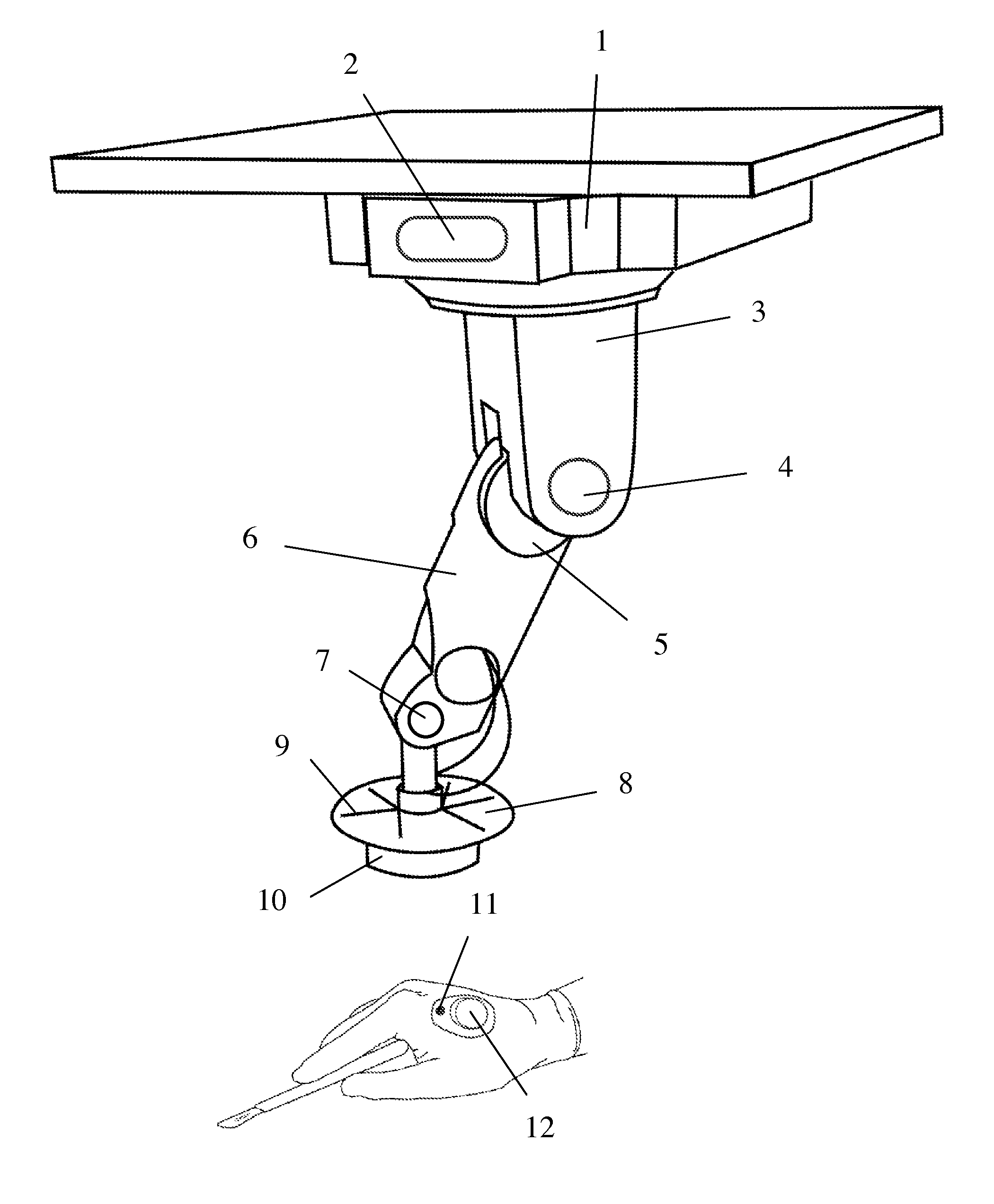
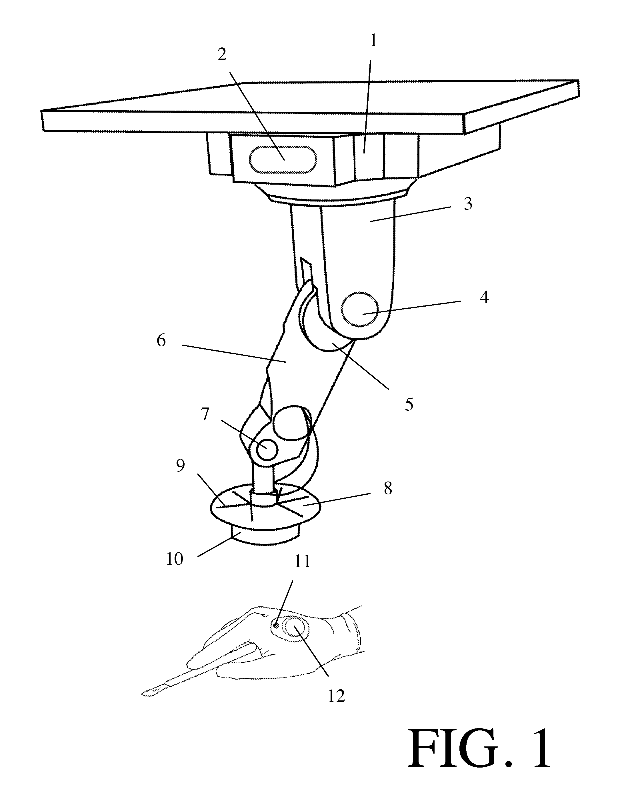
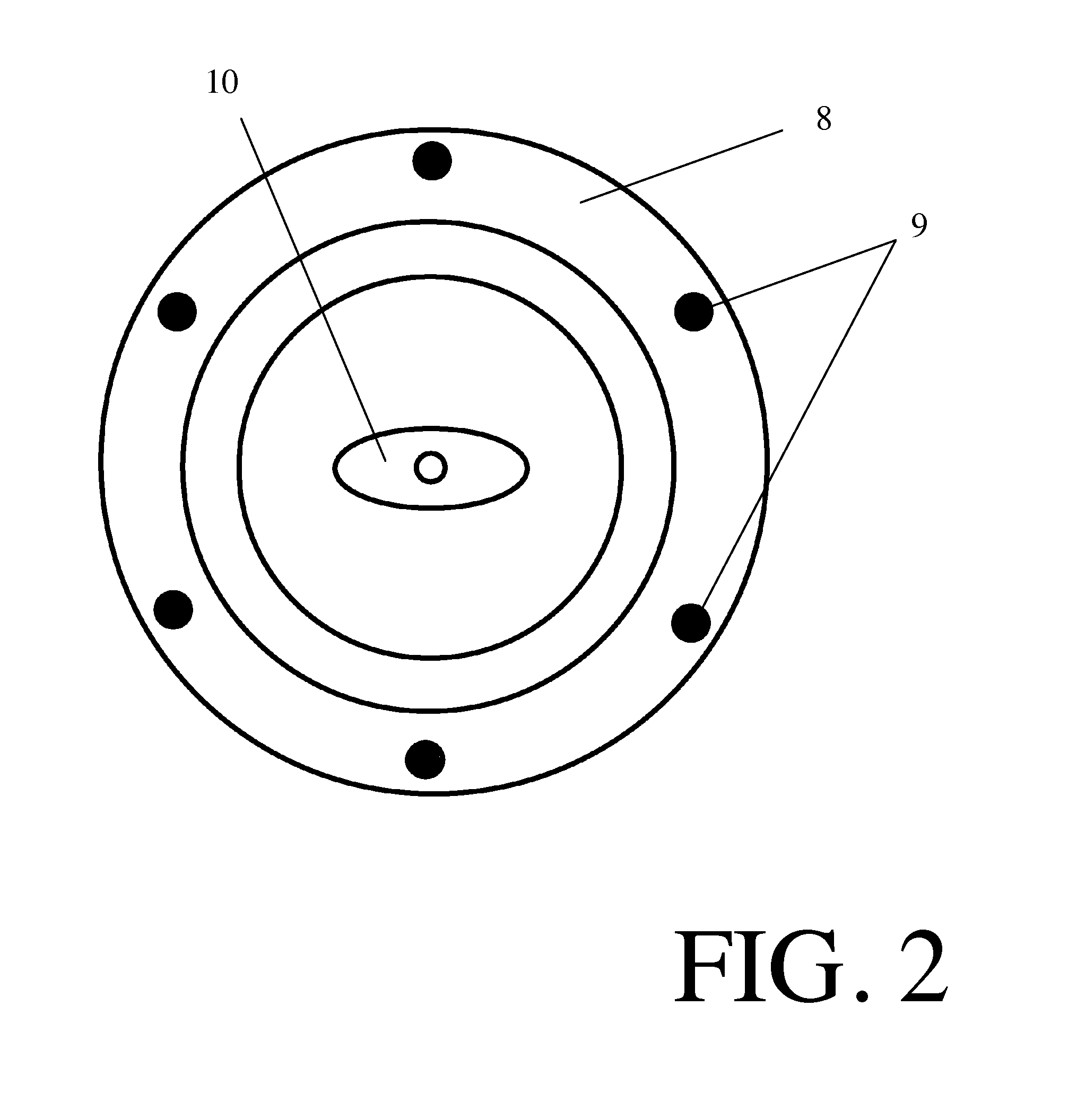
[0026]FIG. 1 and FIG. 2 illustrate an automated surgical illumination system according to one embodiment of the present invention. The base 1 of the device is to be mounted to the ceiling. Attached to the base 1 is the upper arm segment 3. The upper arm segment 3 rotates 360 degrees both clockwise and counterclockwise on its axis within base 1. Upper arm segment 3 is able to rotate in said manner when motor 2 is turned on in either direction. Attached to the upper arm segment 3 at hinge 5 is lower arm segment 6. Lower arm segment 6 rotates 180 degrees both clockwise and counterclockwise at hinge 5. Lower arm segment 6 is able to rotate in said manner when motor 4 is turned on in either direction. At the end of lower arm attaches a third motor 7 that gives the cone the third range of motion. The lamp reflective cone 8 also functions as a stage for several sensors 9 mounted to the cone 8 to form a sensor array. The light source 10 is affixed and centered inside the reflective cone 8.

[...


PUM


Abstract

The present invention provides illumination for a surgical procedure. Using an optical tracking system, the illumination is made to automatically track an optical marker on a surgical glove worn by a clinician to provide more consistent illumination for a surgical procedure.

Description

CROSS-REFERENCES[0001]The present application claims the benefit of priority to U.S. Provisional Application No. 61 / 471,714 (filed 5 Apr. 2011), which is incorporated by reference herein.TECHNICAL FIELD[0002]The present invention relates to surgical lighting systems.BACKGROUND OF THE INVENTION[0003]It is generally believed that it would be desirable to produce a surgical lighting system that can eliminate the need for a surgeon or scrub nurse to manually move a surgical light with their hands to provide focused lighting at the surgical site. Such a system would prevent undue contamination of instruments as a result of transfer of bacterium from lamp handles, allow surgical personnel to focus their attention to more important tasks such as instrument passing, and alleviate the need for low-hanging, reachable lamp handles which may obstruct the surgical flow.[0004]There exist several different approaches to alleviate this problem. U.S. Pat. No. 5,093,769 by Luntsford discloses a surgi...

Claims


Application Information

Patent Timeline
IPC IPC(8): A61B1/06A61G15/00A61G7/00
CPCA61B19/04A61B19/5202A61B2019/5479A61B2019/5437A61B2019/5255A61B42/00A61B42/10A61B90/30A61B2034/2055A61B2090/3937A61B2090/3979
Inventor KIM, GABRIEL M.CHEN, TIFFANY LITIEN
Owner KIM GABRIEL MIN
Why Eureka
Try Eureka