Magnetic clutch for the transmission of tightening torque

a technology of torque transmission and magnetic clutch, which is applied in the direction of dynamo-electric machines, caps, and closures using caps, etc., can solve the problems of cap being blocked in an undesired manner, the cap may remain improperly closed, and the clutch components are worn mor

Inactive Publication Date: 2012-10-18
ANTONIO MENGIBAR
View PDF3 Cites 15 Cited by
  • Summary
  • Abstract
  • Description
  • Claims
  • Application Information

AI Technical Summary

Benefits of technology

[0010]In order to solve the aforementioned problems, the magnetic clutch for the transmission of tightening torque of the present invention comprises a first shaft integral to a casing in whose interior there is a second shaft coaxial to the first shaft. Said second shaft is fixed to the casing by mechanical means that allow its free rotation movement relative thereto, being both shafts engaged together by magnetic attraction to transmit the tightening torque. The configuration described above maintains the symmetry principle, being it possible for each one of the shafts to independently act as a driving shaft or a driven shaft.

Problems solved by technology

By contrast, the hammering may produce gripping failures of the elements that clamp the cap, making them slide on it and thus damaging it, as well as undesired vibrations that generate greater wear on the clutch components.
While by contrast, as no intermittent force peaks are produced, the cap may either remain improperly closed or be blocked in an undesired position of the container neck.

Method used


Image

  • Magnetic clutch for the transmission of tightening torque
  • Magnetic clutch for the transmission of tightening torque
  • Magnetic clutch for the transmission of tightening torque

Examples


Embodiment Construction

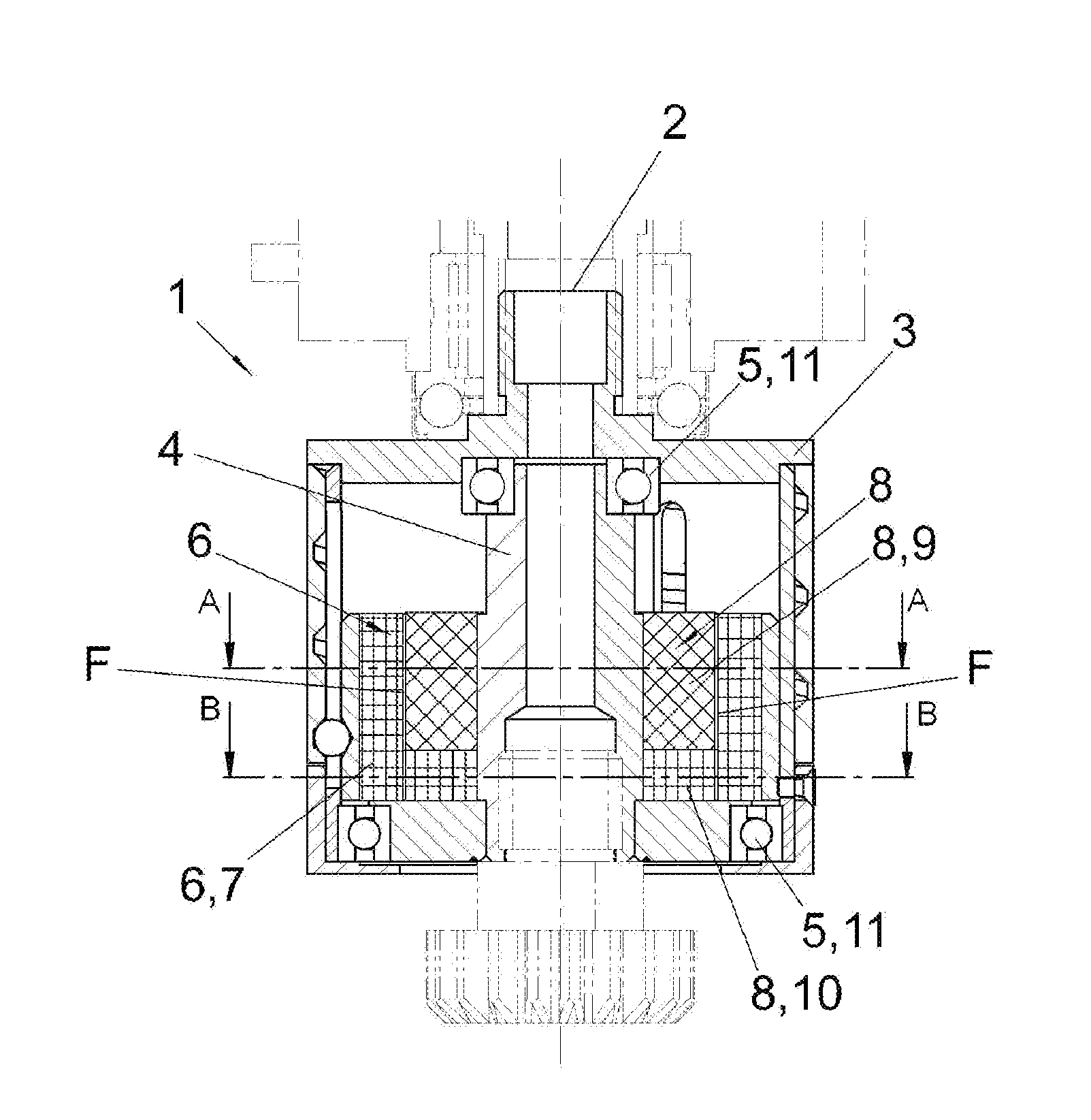
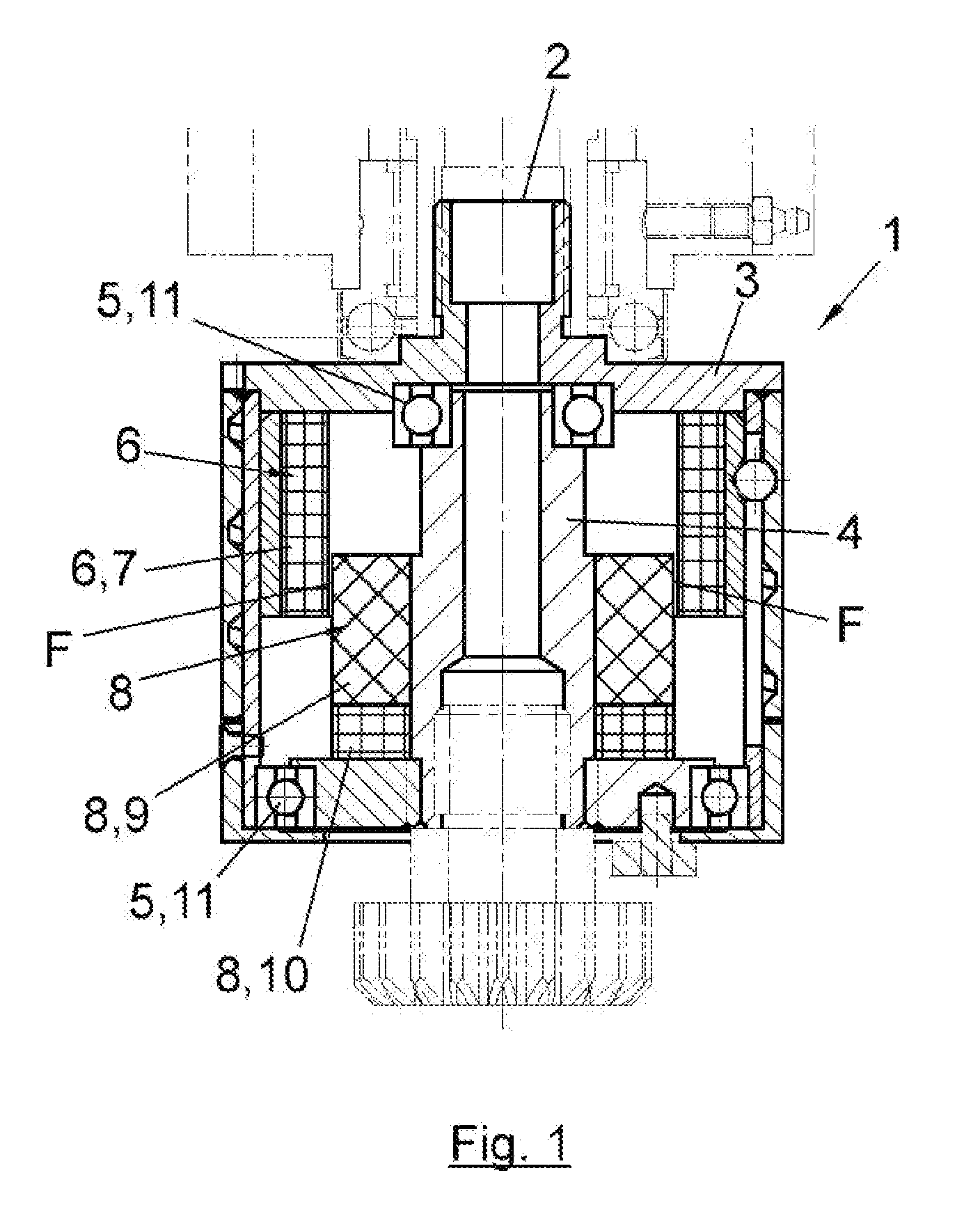
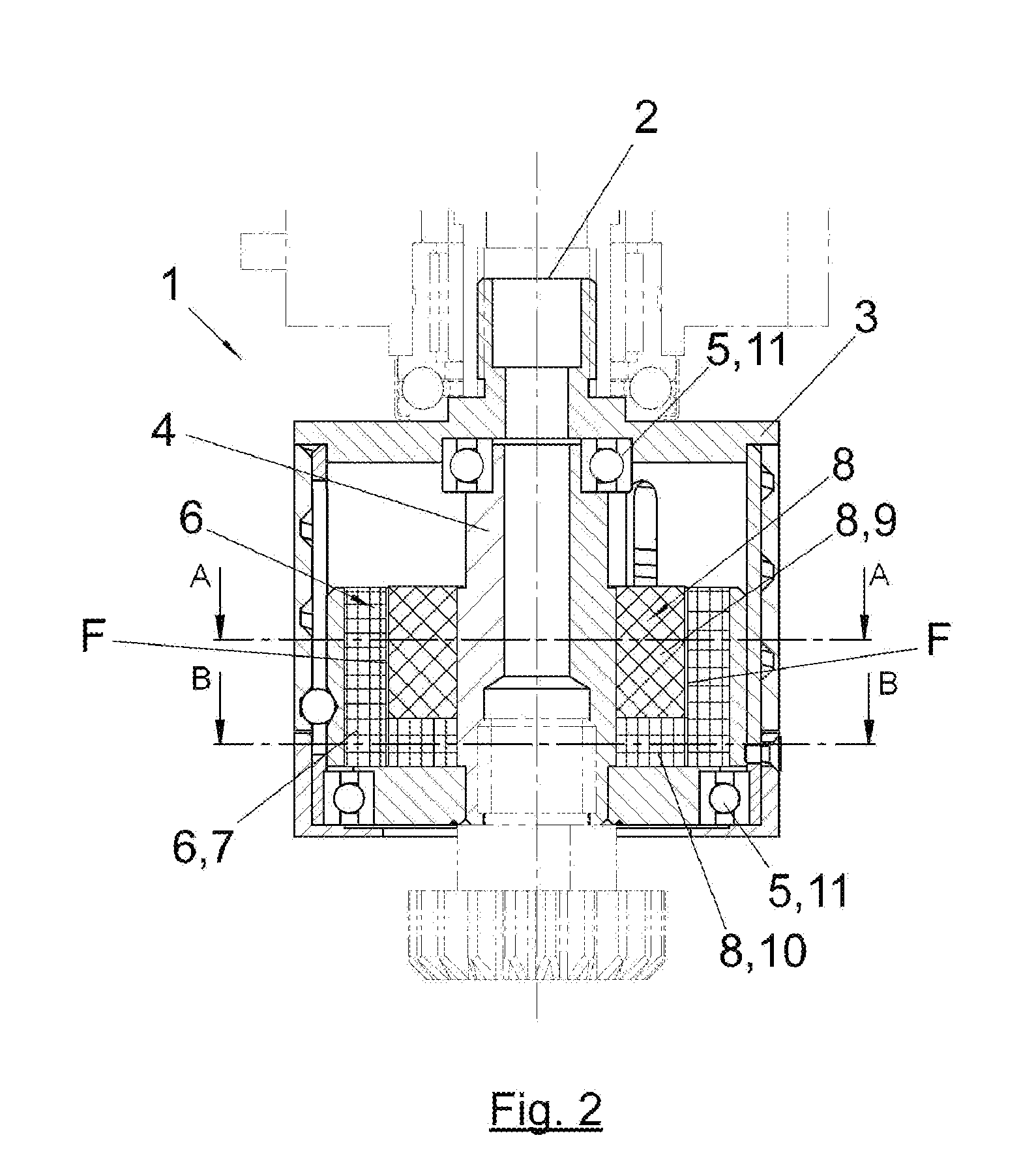
[0030]FIGS. 1 and 2 show an elevation view of the magnetic clutch of the present invention, according to a first preferred embodiment, in which the simple clutch position and the mixed clutch position are shown respectively.

[0031]In these figures it can be seen that the magnetic clutch (1) for the transmission of tightening torque of the present invention comprises a first shaft (2) integral to a casing (3) in whose interior there is a second shaft (4) coaxial to the first shaft (2). Said second shaft (4) is fixed to the casing (3) by mechanical means (5) that allow its free rotation movement relative thereto, being both shafts (2, 4) engaged together by magnetic attraction to transmit tightening torque.

[0032]The magnetic clutch (1) comprises in turn a first and a second magnetic assembly (6, 8). In the present embodiment example, the first magnetic assembly (6) is linked to the first shaft (2), which acts as a driving shaft, while the second magnetic assembly (8) is linked to the s...


PUM


Abstract

Magnetic clutch for the transmission of tightening torque that comprises a first shaft (2) integral to a casing (3) in whose interior there is a second shaft (4) coaxial to the first shaft (2) that is fixed to the casing (3). The shafts (2, 4) are engaged together by magnetic attraction to transmit tightening torque, the clutch (1) includes a first magnetic assembly (6), linked to one of the shafts (2, 4), formed by a first group of magnets (7) of high magnetic coercivity and a second magnetic assembly (8), linked to the remaining shaft (2, 4), formed by a magnet (9) of low magnetic coercivity and by a second group of magnets (10) of high magnetic coercivity adjacent in axial direction to the magnet (9). The first magnetic assembly (6) and the second magnetic assembly (8) present a facing surface (F) in a radial direction.

Description

[0001]This application claims benefit of Ser. No. 1138207.9, filed 24, Mar. 2011 in Europe and which application is incorporated herein by reference. To the extent appropriate, a claim of priority is made to the above disclosed application.FIELD OF THE INVENTION[0002]The present invention relates to a hybrid magnetic clutch for the transmission of tightening torque, which combines the advantages and benefits of the hysteresis magnetic clutches and the magnetic synchronous clutches.[0003]The present invention has been especially designed for its application in the industrial sector in general, being particularly appropriate in the packaging industry to close containers that use screw caps, and more generally for any application that requires tightening torque.BACKGROUND OF THE INVENTION[0004]The magnetic clutches for the transmission of tightening torque are frequently used in the packaging industry, one of its more usual applications being its use for screwing caps on container neck...

Claims


Application Information

Patent Timeline
Patent Type & Authority Applications(United States)
IPC IPC(8): H02K49/06
CPCH02K49/106B67B3/2086
Inventor MENGIBAR RIVAS, ANTONIO
Owner ANTONIO MENGIBAR
Why Eureka
Try Eureka