Compact interaction chamber with multiple cross micro impinging jets

a technology of interfacial chamber and cross-micro, which is applied in the direction of mixing, transportation and packaging, chemistry apparatus and processes, etc., can solve the problem of high energy dissipation

Active Publication Date: 2012-10-18
MICROFLUIDICS INT
View PDF18 Cites 17 Cited by
  • Summary
  • Abstract
  • Description
  • Claims
  • Application Information

AI Technical Summary

Problems solved by technology

In current mixing chambers, the flow from each parallel fluid path collides with the flow from the respective opposite-

Method used


Image

  • Compact interaction chamber with multiple cross micro impinging jets
  • Compact interaction chamber with multiple cross micro impinging jets
  • Compact interaction chamber with multiple cross micro impinging jets

Examples


Embodiment Construction

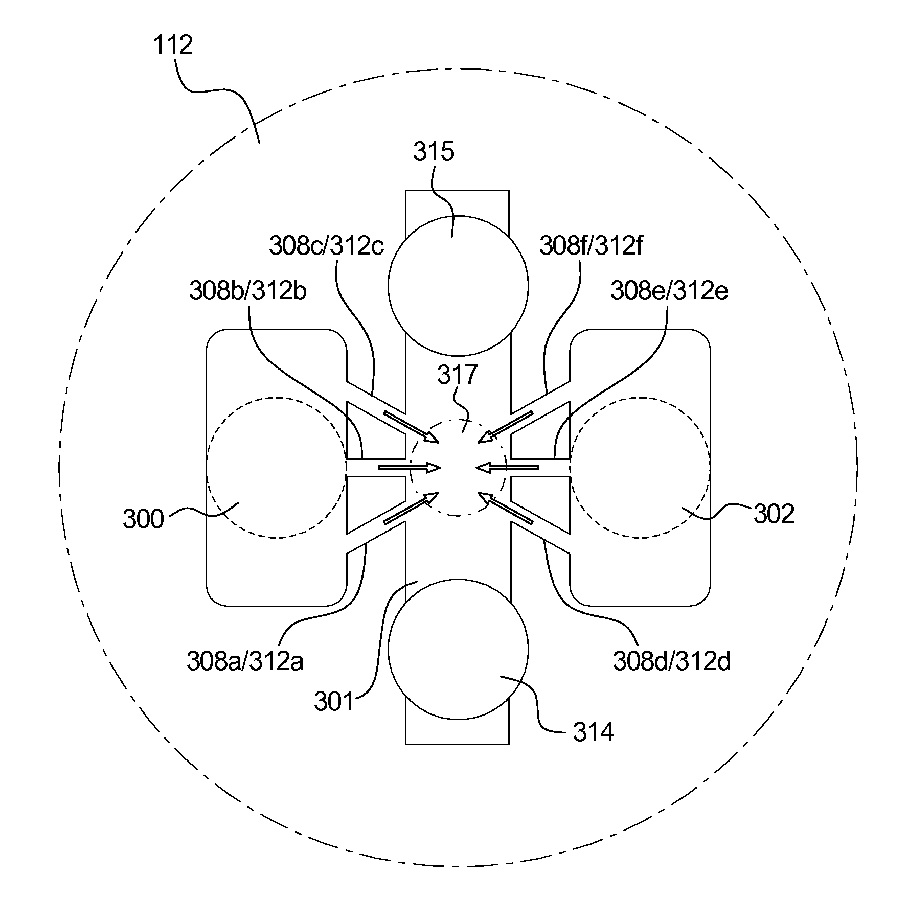
[0016]The present disclosure is generally directed to an interaction chamber that includes mixing chamber elements with a plurality of parallel flow inlets, each of which may be configured to direct fluid along a first parallel path in a first direction, and then along a plurality of second impinging paths in a second direction that may extend substantially perpendicularly to the first direction. Each of the second impinging paths extends from one of the respective first parallel paths. Unlike the plurality of parallel flow paths, the second impinging paths are not arranged parallel to one another, but may be arranged to extend radially outwardly from a concentrated area in the mixing chamber to each of the respective first parallel paths. The orientation of the plurality of second impinging paths cause the multiple fluid flows carried within the paths to converge to the concentrated area in the mixing chamber. By converging each of the multiple fluid flow paths to one single concen...


PUM

PropertyMeasurementUnit
Concentrationaaaaaaaaaa

Abstract

A mixing assembly includes an inlet, an outlet and a mixing chamber, the inlet is fluidly connected to the outlet through a plurality of micro fluid flow paths in a direction perpendicular from the inlet. The micro fluid flow paths fluidly connect to the perpendicular inlet via a transition portion. The micro fluid flow paths are constructed radially inwardly to a concentration area in the mixing chamber. By directing multiple fluid flows to a concentrated area within the mixing chamber at high speeds, the energy dissipated at the point of collision is maximized, which helps to increase consistency and quality of mixing, and to reduce particle size of the fluid in the mixing chamber.

Description

CROSS-REFERENCE TO RELATED APPLICATIONS[0001]This application expressly incorporates by reference, and makes a part hereof, U.S. patent application Ser. No. 12 / 986,477 and the U.S. patent application identified by Attorney Docket Number 0813715.10301, entitled: “Interaction Chamber with Flow Inlet Optimization”, filed on behalf of the same inventors concurrently with the present application.COPYRIGHT NOTICE[0002]A portion of the disclosure of this patent document contains material which is subject to copyright protection. The copyright owner has no objection to the photocopy reproduction of the patent document or the patent disclosure in exactly the form it appears in the Patent and Trademark Office patent file or records, but otherwise reserves all copyright rights whatsoever.BACKGROUND OF THE INVENTION[0003]For certain pharmaceutical applications, manufacturers need to process and mix expensive liquid drugs for testing and production using the lowest possible volume of fluid to sa...

Claims


Application Information

Patent Timeline
IPC IPC(8): B01F15/02
CPCB01F5/0256B01F2215/0032B01F13/0059B01F25/23B01F33/30B01F2101/22B01F23/45
Inventor XIONG, RENQIANGBERNARD, JOHN MICHAEL
Owner MICROFLUIDICS INT
Why Eureka
Try Eureka