Three-phase rectifier circuit

a rectifier circuit and three-phase technology, applied in the direction of power electronics conversion, climate sustainability, power conversion systems, etc., can solve the problems of increased cost and complexity of circuit control, limited output power rate of single-phase systems, and low efficiency and high resonant wave curren

Inactive Publication Date: 2012-10-25
DELTA ELECTRONICS SHANGHAI CO LTD
View PDF2 Cites 16 Cited by
  • Summary
  • Abstract
  • Description
  • Claims
  • Application Information

AI Technical Summary

Benefits of technology

[0022]In one embodiment, the voltage source

Problems solved by technology

However, the output power rate of the single phase system is limited.
A simple circuitry layout of the three-phase PFC circuit is always preferred, but the simple circuitry layout generally leads to problems such as relatively low efficiency and high resonant wave current.
On the other hand, adopting more complicated circuitry layouts to increase the efficiency of the three-phase PFC circuits would create a different set of problems, such as increased cost and complexity o

Method used


Image

  • Three-phase rectifier circuit
  • Three-phase rectifier circuit
  • Three-phase rectifier circuit

Examples


Embodiment Construction

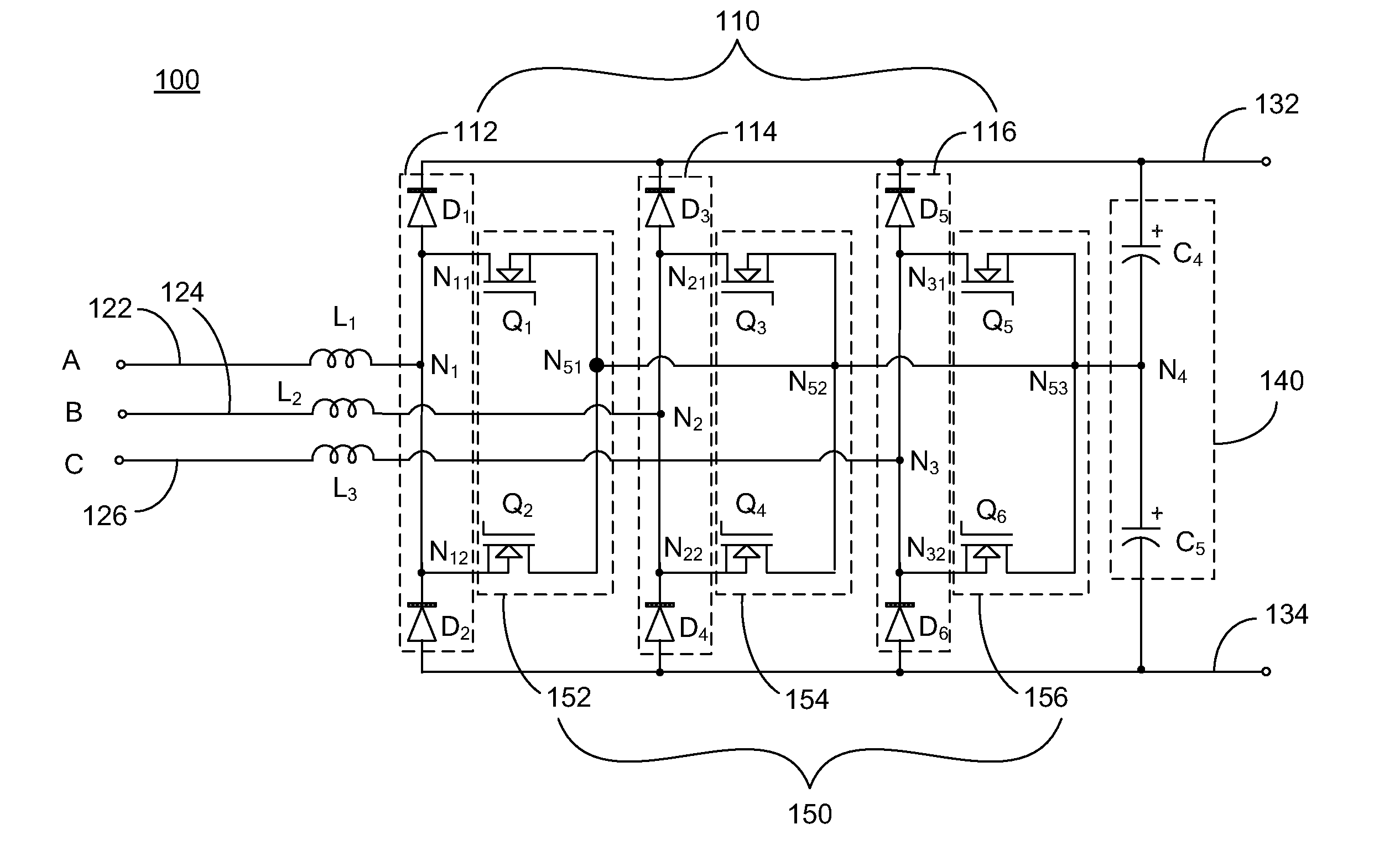
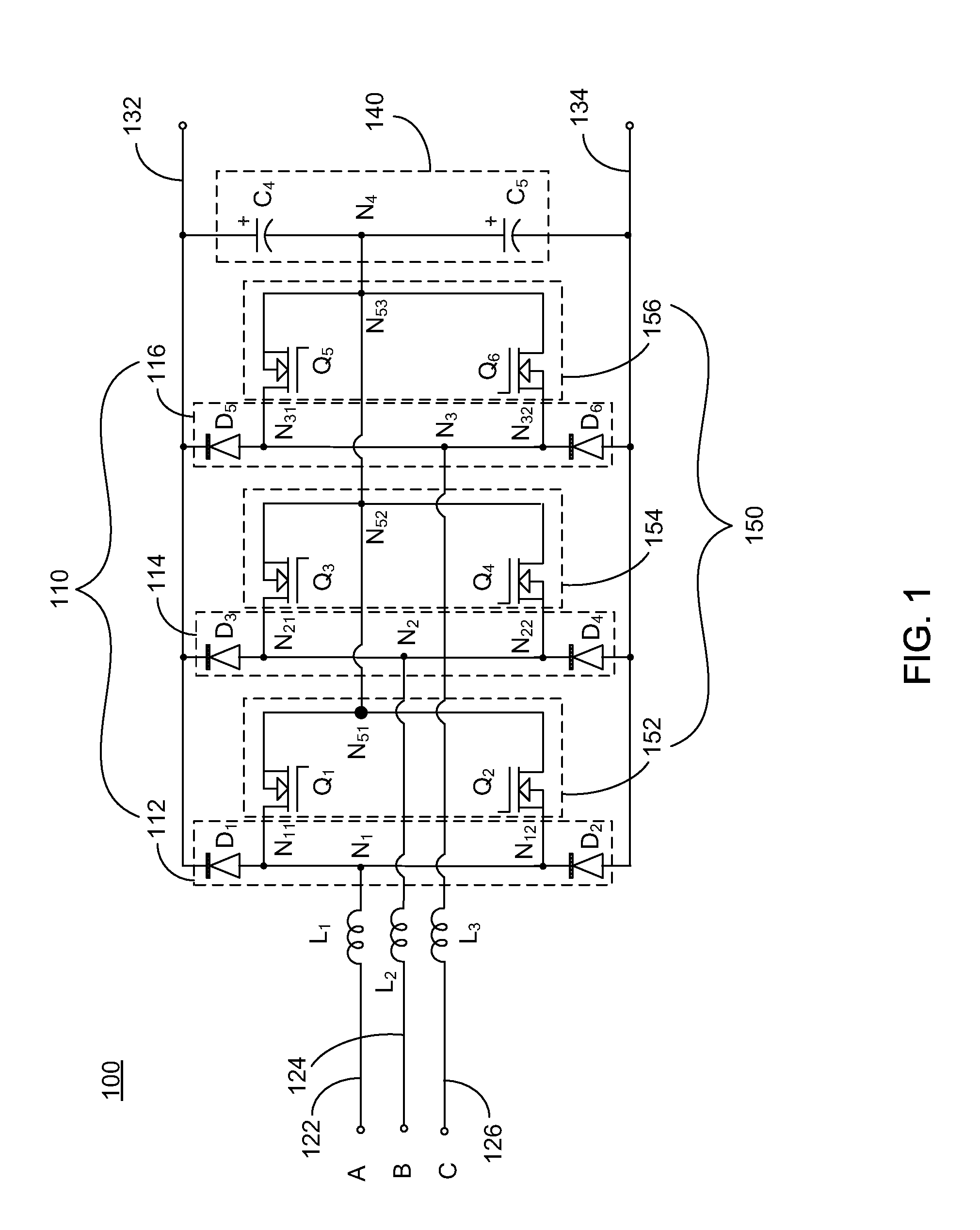
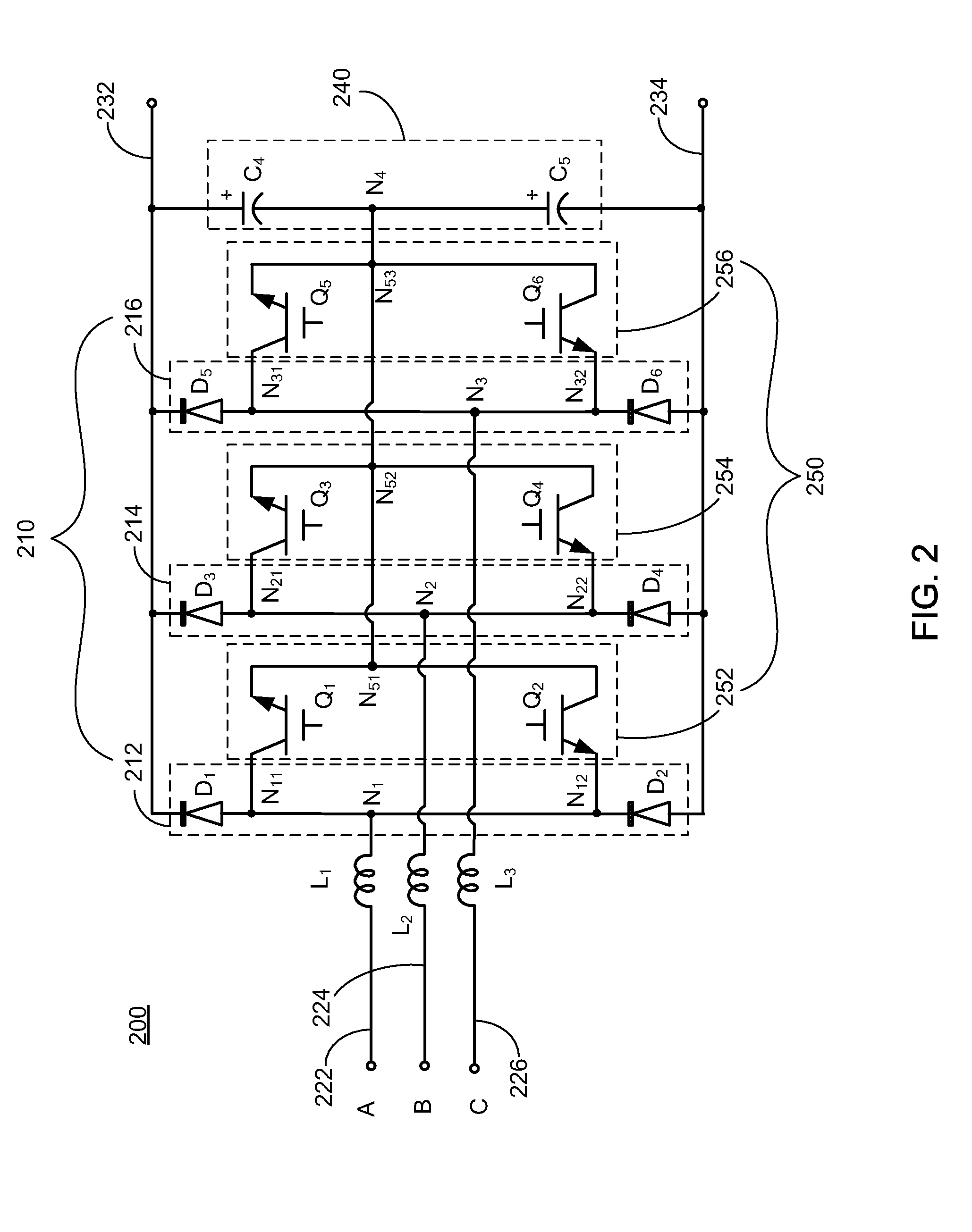
[0031]The present invention will now be described more fully hereinafter with reference to the accompanying drawings, in which exemplary embodiments of the invention are shown. This invention may, however, be embodied in many different forms and should not be construed as limited to the embodiments set forth herein. Rather, these embodiments are provided so that this disclosure will be thorough and complete, and will fully convey the scope of the invention to those skilled in the art. Like reference numerals refer to like elements throughout.

[0032]The terminology used herein is for the purpose of describing particular embodiments only and is not intended to be limiting of the invention. As used herein, the singular forms “a”, “an” and “the” are intended to include the plural forms as well, unless the context clearly indicates otherwise. It will be further understood that the terms “comprises” and / or “comprising,” or “includes” and / or “including” or “has” and / or “having” when used he...


PUM


Abstract

In one aspect of the invention, a three-phase rectifier circuit having three input terminals and two output terminals includes a three-phase diode bridge, three switching circuits, and a voltage source. The three-phase diode bridge has three pairs of first diodes electrically parallel-connected to the two output terminals. Each pair of first diodes has two first diodes series-connected defining a first node therebetween, and electrically connected to a corresponding input terminal at the first node. Each switching circuit has a first terminal, a second terminal and a plurality of switches electrically series-connected between the first and second terminals. The first and second terminals are respectively electrically connected to a second node and a third node, respectively between the first node and the two first diodes of the corresponding pair of first diodes. The voltage source is electrically parallel-connected between the two output terminals and electrically connected to each switching circuit.

Description

CROSS-REFERENCE TO RELATED PATENT APPLICATION[0001]This application is a continuation-in-part application of a co-pending U.S. patent application Ser. No. 13 / 090,925, filed on Apr. 20, 2011, entitled[0002]“PARALLEL-CONNECTED RESONANT CONVERTER CIRCUIT AND CONTROLLING METHOD THEREOF”, by Haoyi Ye et al., which itself is a continuation application of U.S. patent application Ser. No. 12 / 394,571, Feb. 27, 2009, entitled “PARALLEL-CONNECTED RESONANT CONVERTER CIRCUIT AND CONTROLLING METHOD THEREOF”, by Haoyi Ye et al., which status is abandoned and which itself claims priority to and the benefit of, pursuant to 35 U.S.C. §119(a), Taiwan patent application No. 097109222, filed on Mar. 14, 2008, entitled “PARALLEL-CONNECTED RESONANT CONVERTER CIRCUIT AND CONTROLLING METHOD THEREOF”, by Haoyi Ye et al., all of the contents of which are incorporated herein by reference in their entireties.[0003]This application also claims priority to and the benefit of, pursuant to 35 U.S.C. §119(a), Chines...

Claims


Application Information

Patent Timeline
IPC IPC(8): H02M7/06
CPCY02B70/1441H02M7/219Y02B70/10
Inventor YAN, CHAOZHANG, WENXINYE, YIQINGYING, JIANPING
Owner DELTA ELECTRONICS SHANGHAI CO LTD
Why Eureka
Try Eureka