Method of Providing Flow Control Devices for a Production Wellbore

a flow control device and production wellbore technology, applied in the direction of borehole/well accessories, analogue and hybrid computing, instruments, etc., can solve the problems of reducing the amount and quality of produced oil, fluid between the formation and the wellbore may not flow evenly through the flow control device, and the device is relatively expensive and includes moving parts

Inactive Publication Date: 2012-11-01
BAKER HUGHES INC
View PDF7 Cites 65 Cited by
  • Summary
  • Abstract
  • Description
  • Claims
  • Application Information

AI Technical Summary

Benefits of technology

[0007]A method of providing a production string for a wellbore formed in a formation is disclosed. The method, in one embodiment, may include: defining a performance criterion for flow of a fluid from a formation into a wellbore; performing a simulation using a processor, a simulation program, a parameter of the fluid, a parameter of the formation and a parameter of the wellbore to determine a first flow characteristic of the flow of the fluid from the formation into the wellbore corresponding to an initial set of flow control devices arranged in the wellbore; performing one or more additional simulations using the processor, the simulation program and the parameters of formation, fluid and wellbore to determine a new flow characteristic of the flow of the fluid from the formation into the wellbore for a new set of flow control devices until a new determined characteristic of the flow of the fluid from the formation into the wellbore meets the performance criterion; and storing results of simulation results relating to the flow control devices in a suitable storage medium.
[0008]In another aspect, a computer-readable medium, accessible to a processor for executing instructions contained in program embedded in the computer-readable medium is provided. In one embodiment, the program may include: instructions to select a performance criterion for flow of a fluid from a formation into a wellbore; instructions to use a simulation program, a parameter of the fluid, a parameter of the formation and a parameter of the wellbore to determine an initial flow characteristic of the flow of the fluid from the formation into the wellbore corresponding to an initial set of flow control devices arranged along the wellbore; instructions, when the performance criterion is not met, to perform one or more simulation using the simulation program, a new set of flow control devices, the formation parameter, fluid parameter and the wellbore parameter to determine a characteristic of the flow of the fluid from the formation into the wellbore that meets the performance criterion; and storing a simulation result relating to the set of flow control devices that meet the performance criterion.
[0009]Examples of the more important features of the disclosure have been summarized rather broadly in order that detailed description thereof that follows may be better understood, and in order that the contributions to the art may be appreciated. There are, of course, additional features of the disclosure that will be described hereinafter and which will form the subject of the claims appended hereto.

Problems solved by technology

Uneven drainage may result in undesirable conditions such as invasion of a gas cone or water cone.
In like fashion, a water cone may cause an in-flow of water into the oil production flow that reduces the amount and quality of the produced oil.
Therefore, fluid between the formation and the wellbore may not flow evenly through the inflow control devices.
Such devices are relatively expensive and include moving parts, which require maintenance and may not be very reliable over the life of the wellbore.

Method used


Image

  • Method of Providing Flow Control Devices for a Production Wellbore
  • Method of Providing Flow Control Devices for a Production Wellbore
  • Method of Providing Flow Control Devices for a Production Wellbore

Examples


Embodiment Construction

[0017]The present disclosure relates to apparatus and methods for controlling flow of formation fluids into a well. The present disclosure provides certain drawings and describes certain embodiments of the apparatus and methods, which are to be considered exemplification of the principles described herein and are not intended to limit the disclosure to the illustrated and described embodiments.

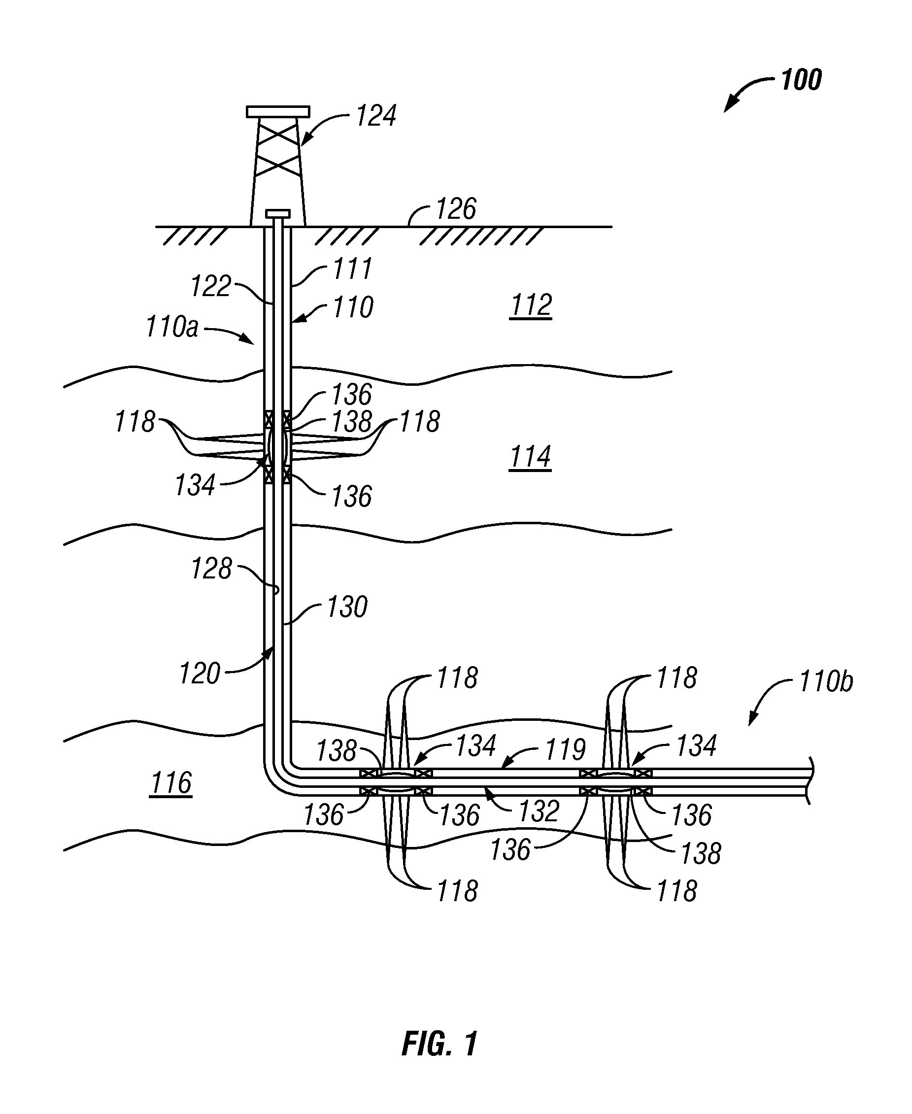
[0018]FIG. 1 shows an exemplary fluid production system 100 that includes a wellbore 110 drilled through an earth 112 and into a pair of production zones or reservoirs 114, 116 from which the production of hydrocarbons is desired. The wellbore 110 is shown lined with a casing 111 having a number of perforations 118 that penetrate and extend into the formations production zones 114, 116 so that production fluids may flow from the production zones 114, 116 into the wellbore 110. The well completion may be cased or open hole and the production devices 134 may be installed in both completion types...


PUM


Abstract

A method of providing a production string for a wellbore formed in a formation is disclosed. The method, in one embodiment may include: defining a performance criterion for flow of a fluid from a formation into a wellbore; performing a simulation using a processor, a simulation program, a parameter of the fluid, a parameter of the formation and a parameter of the wellbore to determine a first flow characteristic of the flow of the fluid from the formation into the wellbore corresponding to an initial set of flow control devices arranged in the wellbore; performing one or more additional simulations using the processor, the simulation program and the parameters of formation, fluid and wellbore to determine a new flow characteristic of the flow of the fluid from the formation into the wellbore for a new set of flow control devices until a new determined characteristic of the flow of the fluid from the formation into the wellbore meets the performance criterion; and storing results of simulation results relating to the flow control devices in a suitable storage medium.

Description

BACKGROUND OF THE DISCLOSURE[0001]1. Field of the Disclosure[0002]The disclosure relates generally to apparatus and methods for control of fluid flow From subterranean formations into a production string in a wellbore.[0003]2. Description of the Related Art[0004]Hydrocarbons such as oil and gas are recovered from a subterranean formation using a well or wellbore drilled into the formation. In some cases the wellbore is completed by placing a casing along the wellbore length and perforating the casing adjacent each production zone (hydrocarbon bearing zone) to extract fluids (such as oil and gas) from such a production zone. In other cases, the wellbore may be open hole. One or more inflow control devices are placed in the wellbore to control flow of fluids into the wellbore. These flow control devices and production zones are generally separated from each other by installing a packer between them. Fluid from each production zone entering the wellbore is drawn into a tubing that runs...

Claims


Application Information

Patent Timeline
Patent Type & Authority Applications(United States)
IPC IPC(8): G06G7/57
CPCE21B43/12E21B43/00
Inventor GARCIA, GONZALO A.GARCIA, LUIS A.RUSSELL, RONNIE D.
Owner BAKER HUGHES INC
Why Eureka
Try Eureka