System for displaying images

a technology for displaying images and systems, applied in semiconductor devices, diodes, electrical devices, etc., can solve the problem of reducing the emission efficiency of emissive display devices with circular polarizers

Active Publication Date: 2012-11-08
INNOLUX CORP
View PDF19 Cites 27 Cited by
  • Summary
  • Abstract
  • Description
  • Claims
  • Application Information

AI Technical Summary

Problems solved by technology

However the transparency of the circular polarizer is about 40% to 50%, such that the e

Method used


Image

  • System for displaying images
  • System for displaying images
  • System for displaying images

Examples


Embodiment Construction

[0013]The following description is of the best-contemplated mode of carrying out the invention. This description is provided for the purpose of illustrating the general principles of the invention and should not be taken in a limiting sense. The scope of the invention is best determined by reference to the appended claims.

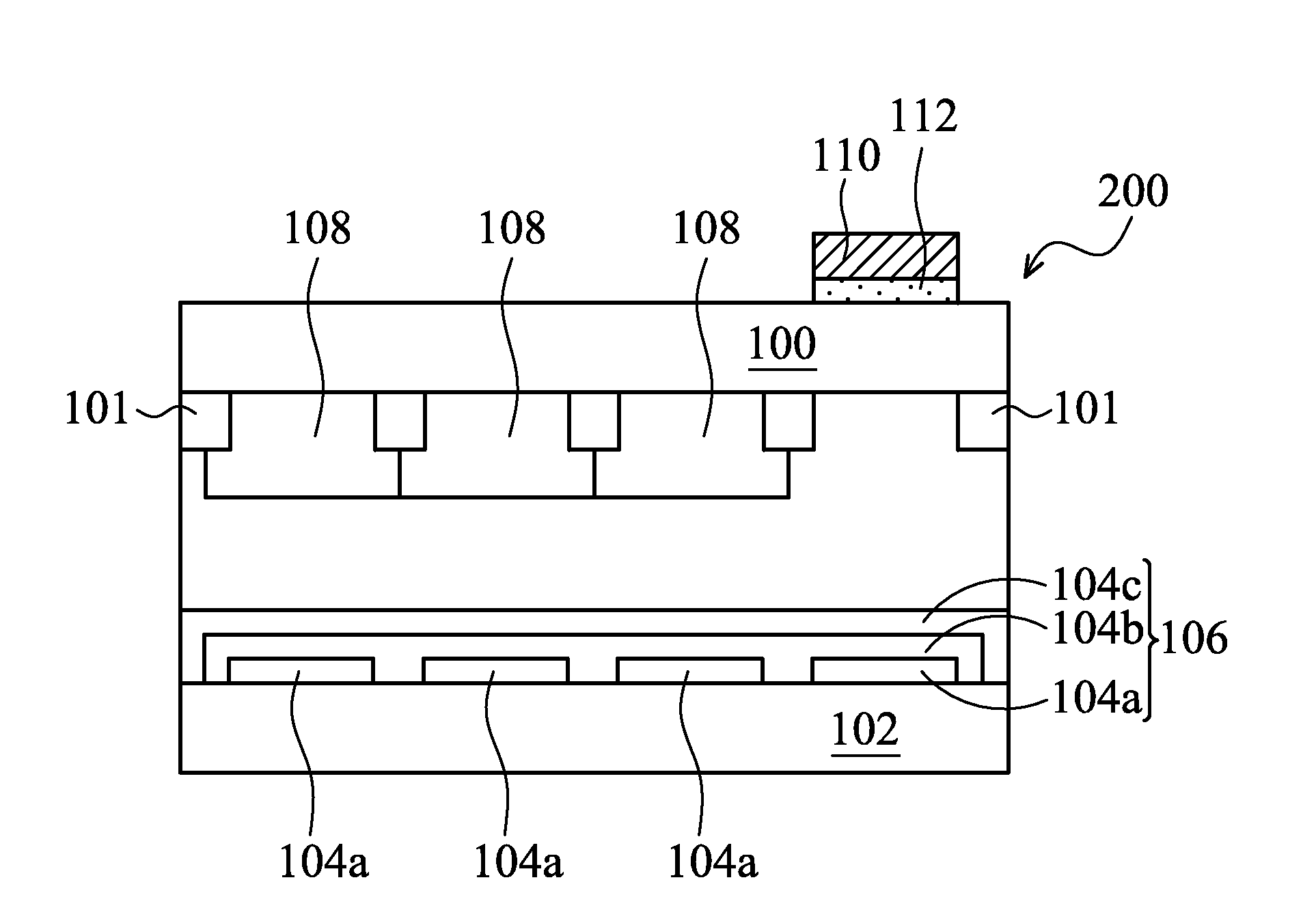
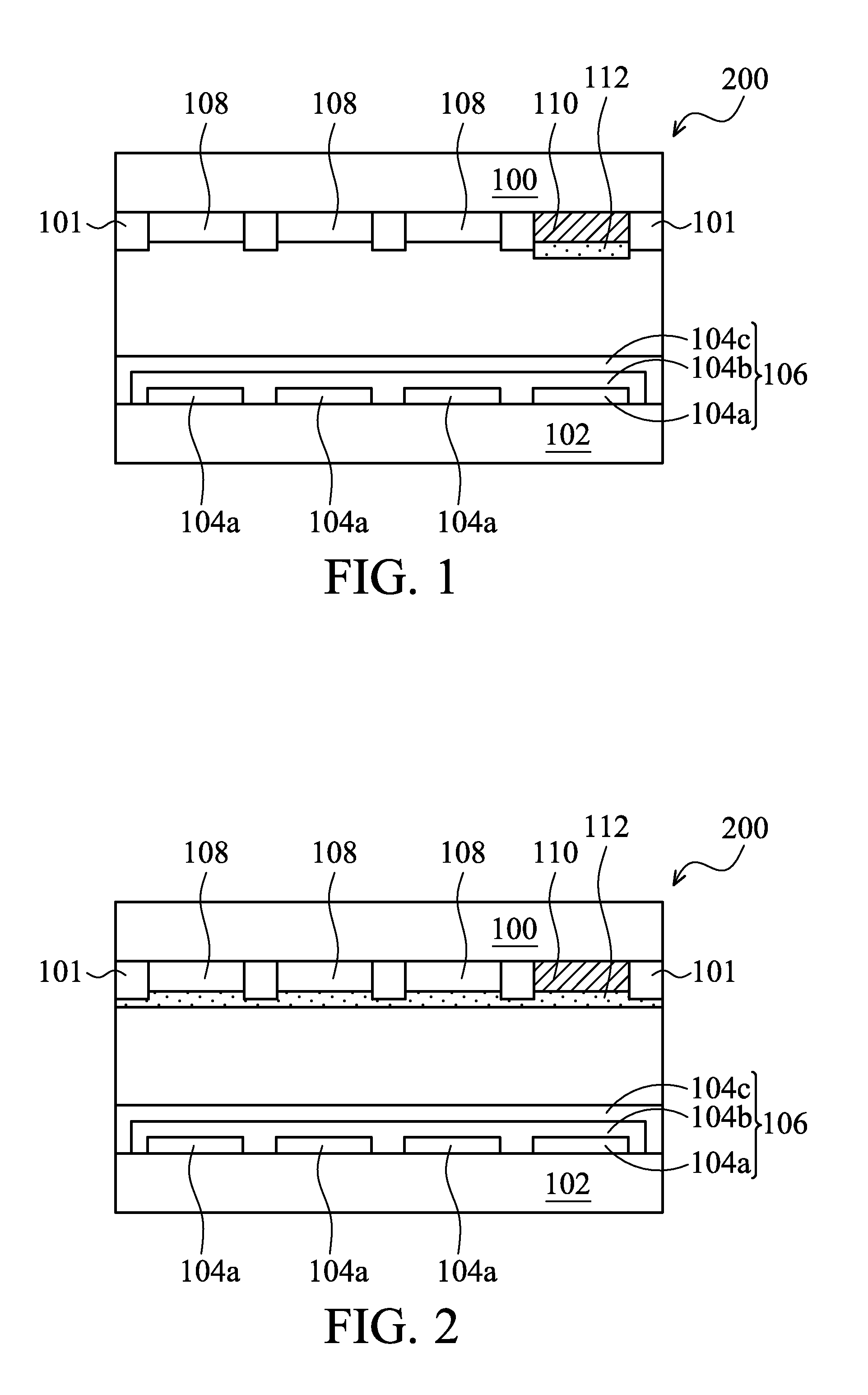
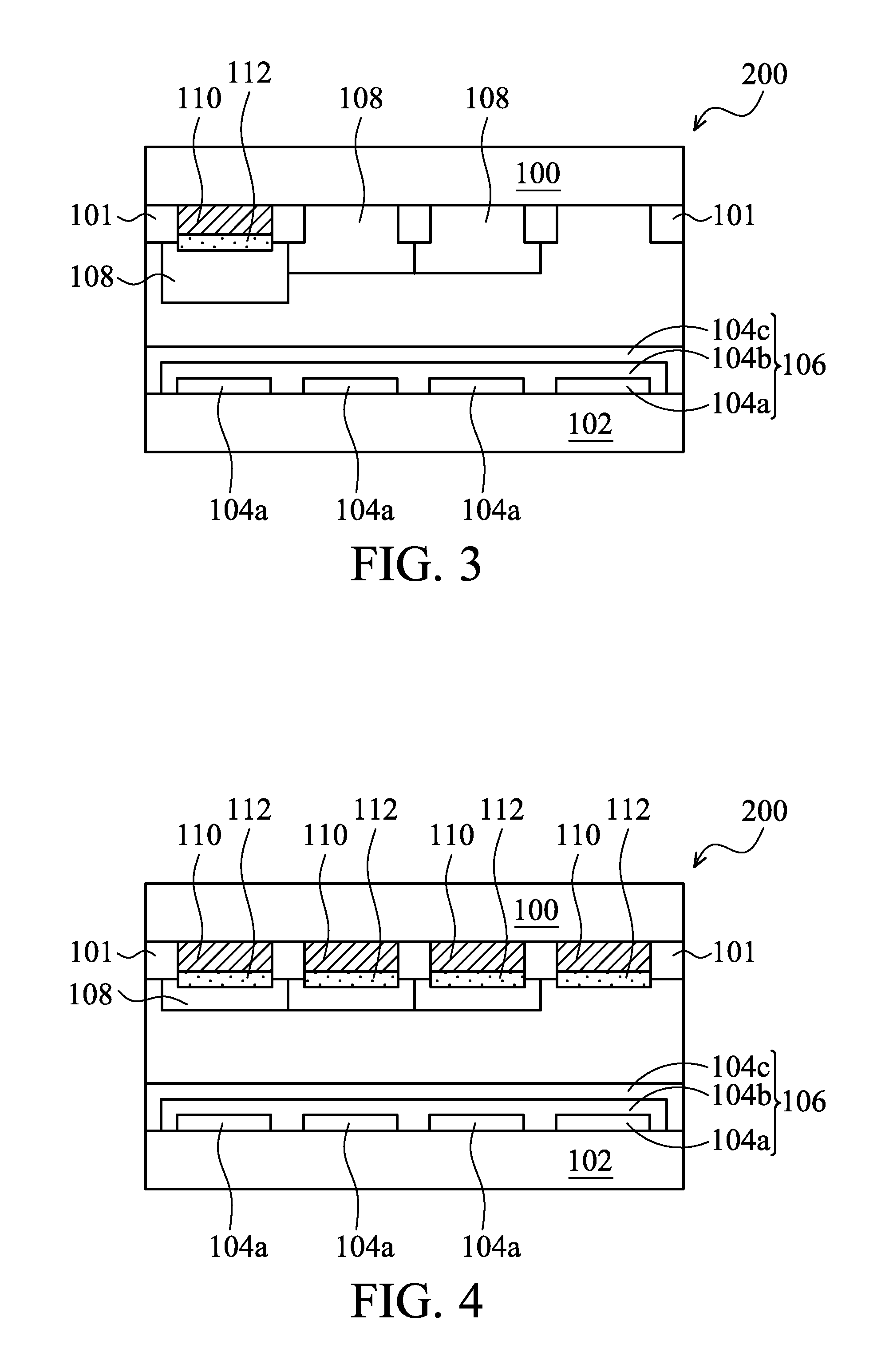
[0014]Systems for displaying images are provided. FIG. 1 illustrates an exemplary embodiment of a system for displaying images according to the invention, and in particular, to a system for displaying images, including an emissive display device 200. In the embodiment, the emissive display device 200 comprises a plurality of pixel elements arranged in an array. Here, in order to simplify the diagram, only a pixel element is depicted. The pixel element comprises a first substrate 100, a second substrate 102, an organic light-emitting device (OLED) 106, at least one patterned polarized film 110, and at least one retarder film 112.

[0015]The first substrate 100 may ser...


PUM


Abstract

A system for displaying images is provided. The system includes an emissive display device including a plurality of pixel elements arranged in an array. Each pixel element includes a first substrate and a second substrate disposed thereunder, wherein the first substrate includes at least three subpixel regions. An organic light-emitting device is disposed between the first and second substrates and on the second substrate. At least one patterned polarizer film is disposed between the first and second substrates to be correspondingly located at one of the subpixel regions. At least one retarder film is disposed between the first and second substrates and affixed to the patterned polarizer film.

Description

BACKGROUND OF THE INVENTION[0001]1. Field of the Invention[0002]The invention relates to a flat panel display (FPD), and in particular to an emissive display device with a polarizer film and a retarder film.[0003]2. Description of the Related Art[0004]Recently, with the development and wide application of electronic products such as mobile phones, PDAs, and notebook computers, there has been an increasing demand for flat panel displays (FPDs) which consume less electric power and occupy less space. Organic light emitting diode (OLEDs) and organic electroluminescent display (OELDs) are self-emissive and highly luminous, with a wide viewing angle, a fast response time, and a simple fabrication process. Thus, OELD / OLED displays have become an industry display of choice.[0005]An OLED typically has a reflector or reflective electrode to enhance the output of emitted light through one side of the OLED. However, the reflector or reflective electrode also reflects ambient light, which cause...

Claims


Application Information

Patent Timeline
IPC IPC(8): H01L27/15
CPCH01L27/3213H01L51/5281H01L27/322H10K59/351H10K59/38H10K50/86
Inventor HATTA, YOSHIHISAWU, PAO-CHUNG
Owner INNOLUX CORP
Why Eureka
Try Eureka