
Methods and apparatus for controlled chemical vapor deposition

a technology control method, which is applied in the direction of chemical vapor deposition coating, metal material coating process, coating, etc., can solve the problems of poor control of vapor material release, unfavorable directional control of exit aperture, and inability to uniformly apply vapor material to the substrate, etc., to achieve the effect of improving distribution and directional control

Active Publication Date: 2012-11-22
THE BF GOODRICH CO
View PDF11 Cites 1 Cited by
  • Summary
  • Abstract
  • Description
  • Claims
  • Application Information

AI Technical Summary

Benefits of technology

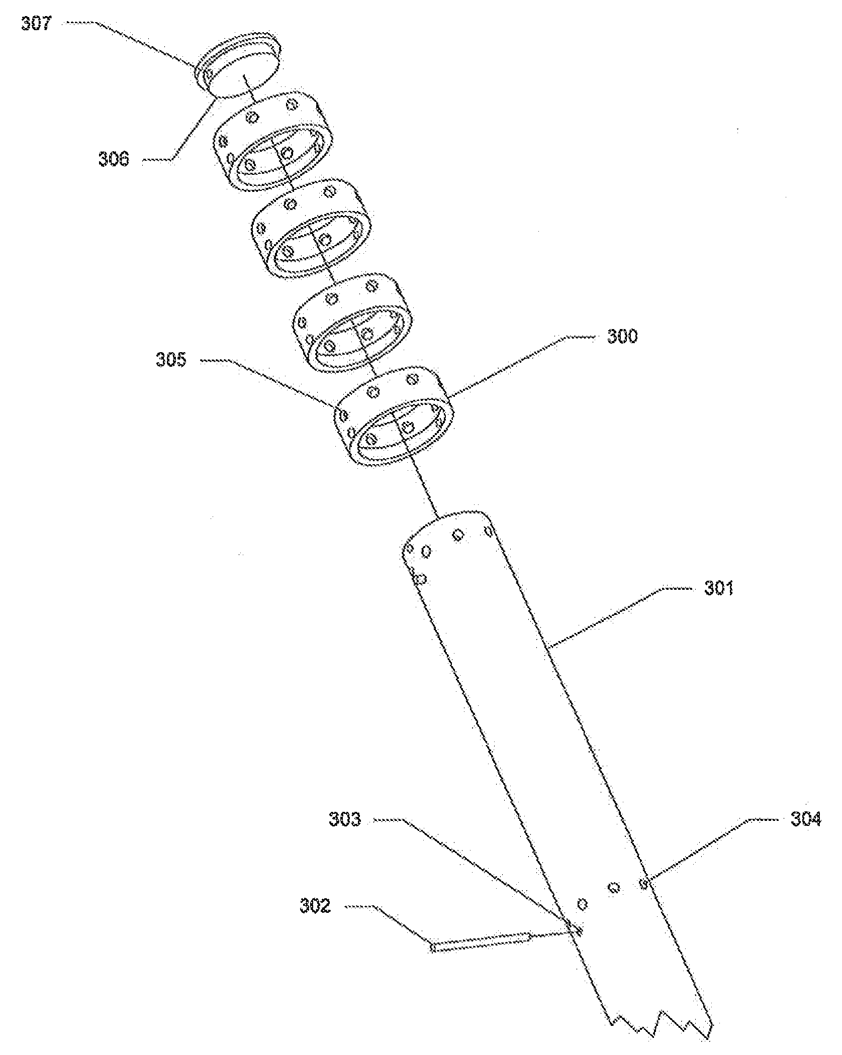
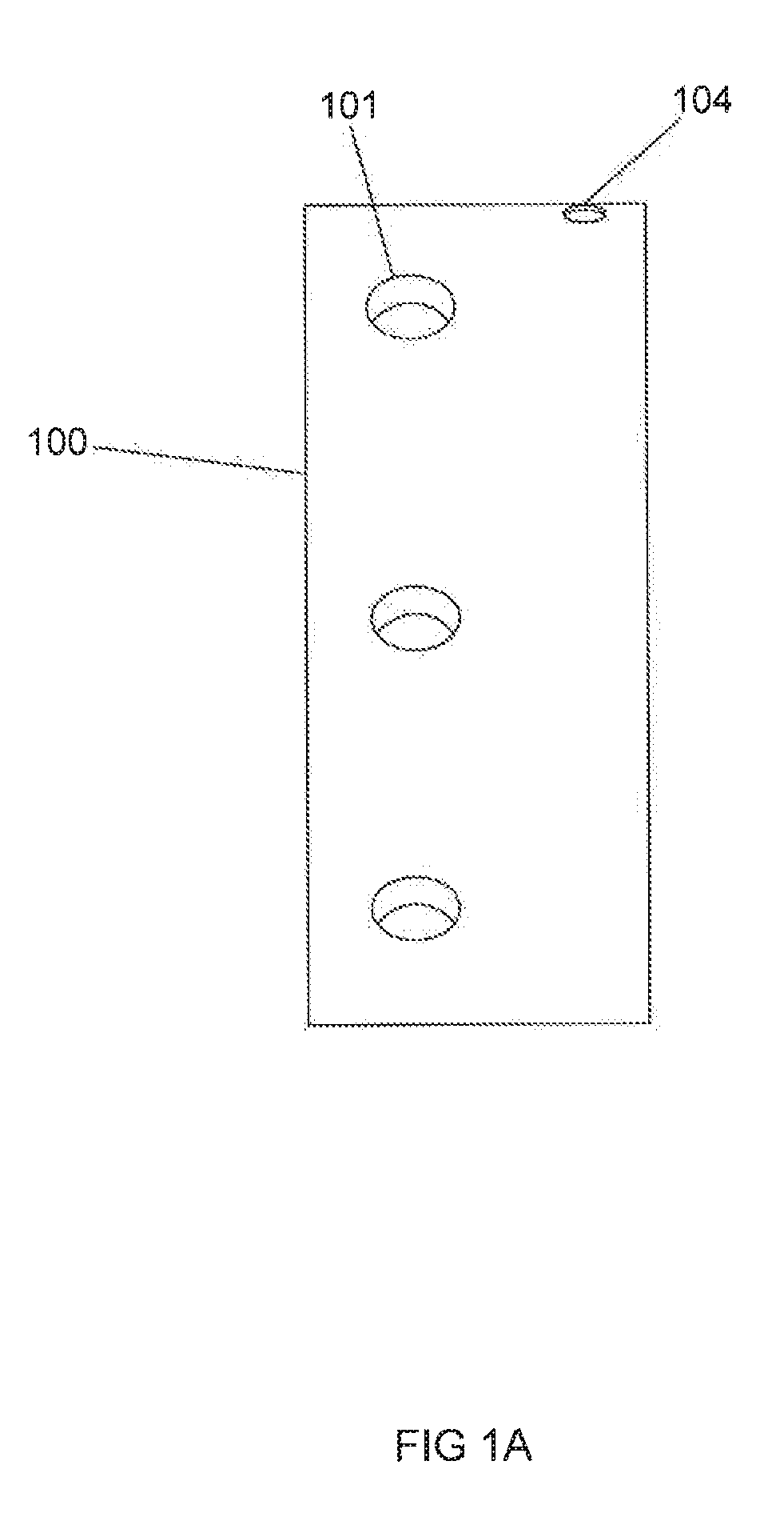
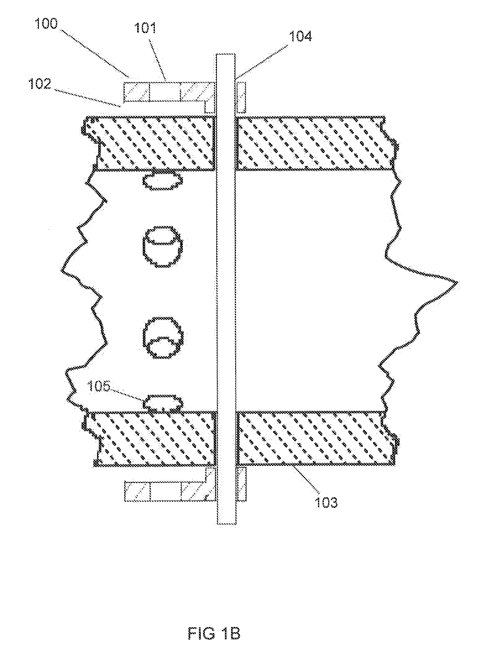
The gas injector system described in this patent improves the distribution and control of vapor material in chemical vapor deposition or chemical vapor infiltration processes. It prevents clogging of the gas injector tubes and allows the vapor material to flow both horizontally and vertically. The system includes a gas injector tube with a tube aperture, a shield collar with a collar aperture, and a coupling mechanism to connect the gas injector tube and shield collar. The system also includes a first and second gas injector tube that are coaxially aligned at a tube joint with a gap between them. The technical effects of this system include improved distribution and directional control of vapor material, reduced clogging of gas injector tubes, and improved process efficiency.

Problems solved by technology

However, there are disadvantages associated with such conventional systems and methods for performing CVD.
In some conventional systems, vapor material release is poorly controlled and may not be uniformly applied to the substrate.
For example, exit apertures may become clogged.
Although in some instances, a clogged tube may be re-machined to unclog the holes, in many cases, replacement of the tube is necessary, limiting the useful life of the tube.

Method used


Image

  • Methods and apparatus for controlled chemical vapor deposition
  • Methods and apparatus for controlled chemical vapor deposition
  • Methods and apparatus for controlled chemical vapor deposition

Examples


Embodiment Construction

[0024]The detailed description of exemplary embodiments herein makes reference to the accompanying drawings, which show exemplary embodiments by way of illustration and its best mode, and not of limitation. While these exemplary embodiments are described in sufficient detail to enable those skilled in the art to practice the invention, it should be understood that other embodiments may be realized and that logical, chemical and mechanical changes may be made without departing from the spirit and scope of the invention. For example, the steps recited in any of the method or process descriptions may be executed in any order and are not necessarily limited to the order presented. Moreover, many of the functions or steps may be outsourced to or performed by one or more third parties. Furthermore, any reference to singular includes plural embodiments, and any reference to more than one component or step may include a singular embodiment or step. Also, any reference to attached, fixed, co...


PUM

PropertyMeasurementUnit
pressuresaaaaaaaaaa
temperaturesaaaaaaaaaa
thickaaaaaaaaaa

Abstract

A gas injector system is provided that allows for improved distribution and directional control of the vapor material in a CVD or CVI process. Gas injector systems may be used without experiencing significant clogging of gas injector tube apertures over multiple. CVD procedures. Further, a gas injector system provided includes a dual aperture release system and / or allow vapor material to flow both substantially horizontally and substantially vertically.

Description

CROSS REFERENCE TO RELATED APPLICATIONS[0001]The present application claims priority to and is a divisional application of U.S. patent application Ser. No. 12 / 395,414, filed Feb. 27, 2009 and entitled, “METHODS AND APPARATUS FOR CONTROLLED CHEMICAL VAPOR DEPOSITION.” The '414 Application is incorporated by reference in its entirety.FIELD OF INVENTION[0002]The present invention relates to chemical vapor infiltration (CVI) and chemical vapor deposition (CVD), more particularly, apparatus and methods for gas injectors used in conjunction with CVD / CVI and gas injector systems that have extended useful lives.BACKGROUND OF THE INVENTION[0003]Chemical vapor infiltration (CVI) and chemical vapor deposition (CVD) are well-known processes for forming composite materials. CVI / CVD are particularly useful processes for fabricating structural composites such as brake disks, combustors and turbine components, and CVD / CVI are also used to fabricate various semiconductor products and other electroni...

Claims


Application Information

Patent Timeline
Patent Type & Authority Applications(United States)
IPC IPC(8): C23C16/455
CPCC23C16/045Y10T29/49945C23C16/45591C23C16/45578
Inventor FRY, VINCENT
Owner THE BF GOODRICH CO
Learn More