Select-fire stackable gun system

a gun system and gun string technology, applied in the field of oil and gas production, can solve the problems of limiting the height of the lubricator and the length of the gun string

Active Publication Date: 2012-11-29
BAKER HUGHES INC
View PDF15 Cites 72 Cited by
  • Summary
  • Abstract
  • Description
  • Claims
  • Application Information

AI Technical Summary

Problems solved by technology

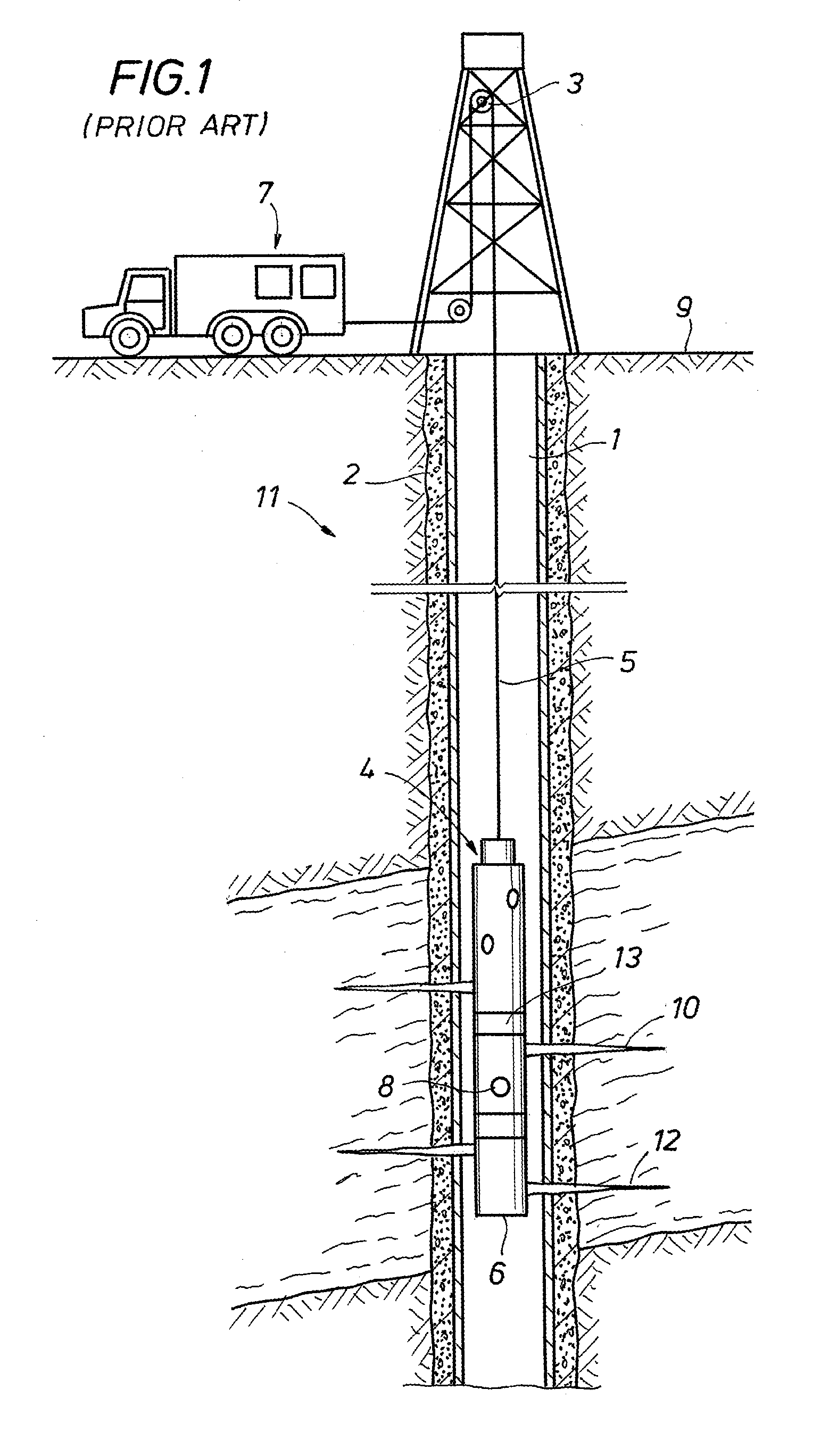
In some instances space constraints at the well site may limit the height of the lubricator thereby in turn limiting the length of the gun string 4.

Method used


Image

  • Select-fire stackable gun system
  • Select-fire stackable gun system
  • Select-fire stackable gun system

Examples


Embodiment Construction

[0019]The method and system of the present disclosure will now be described more fully hereinafter with reference to the accompanying drawings in which embodiments are shown. The method and system of the present disclosure may be in many different forms and should not be construed as limited to the illustrated embodiments set forth herein; rather, these embodiments are provided so that this disclosure will be thorough and complete, and will fully convey its scope to those skilled in the art. Like numbers refer to like elements throughout.

[0020]It is to be further understood that the scope of the present disclosure is not limited to the exact details of construction, operation, exact materials, or embodiments shown and described, as modifications and equivalents will be apparent to one skilled in the art. In the drawings and specification, there have been disclosed illustrative embodiments and, although specific terms are employed, they are used in a generic and descriptive sense onl...


PUM


Abstract

A system and method of perforating by stacking a perforating string within a wellbore, then deploying the perforating string to a designated depth for detonating shaped charges in the perforating string. The string can be formed by anchoring a single perforating gun in the wellbore, then landing subsequent guns on one another atop the anchored gun. Wet connects on the ends of the perforating guns enable mechanical engagement of each adjacent gun as well as signal communication through the connections.

Description

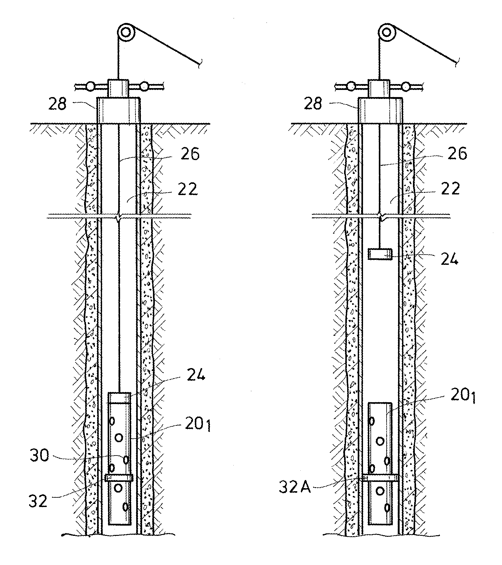
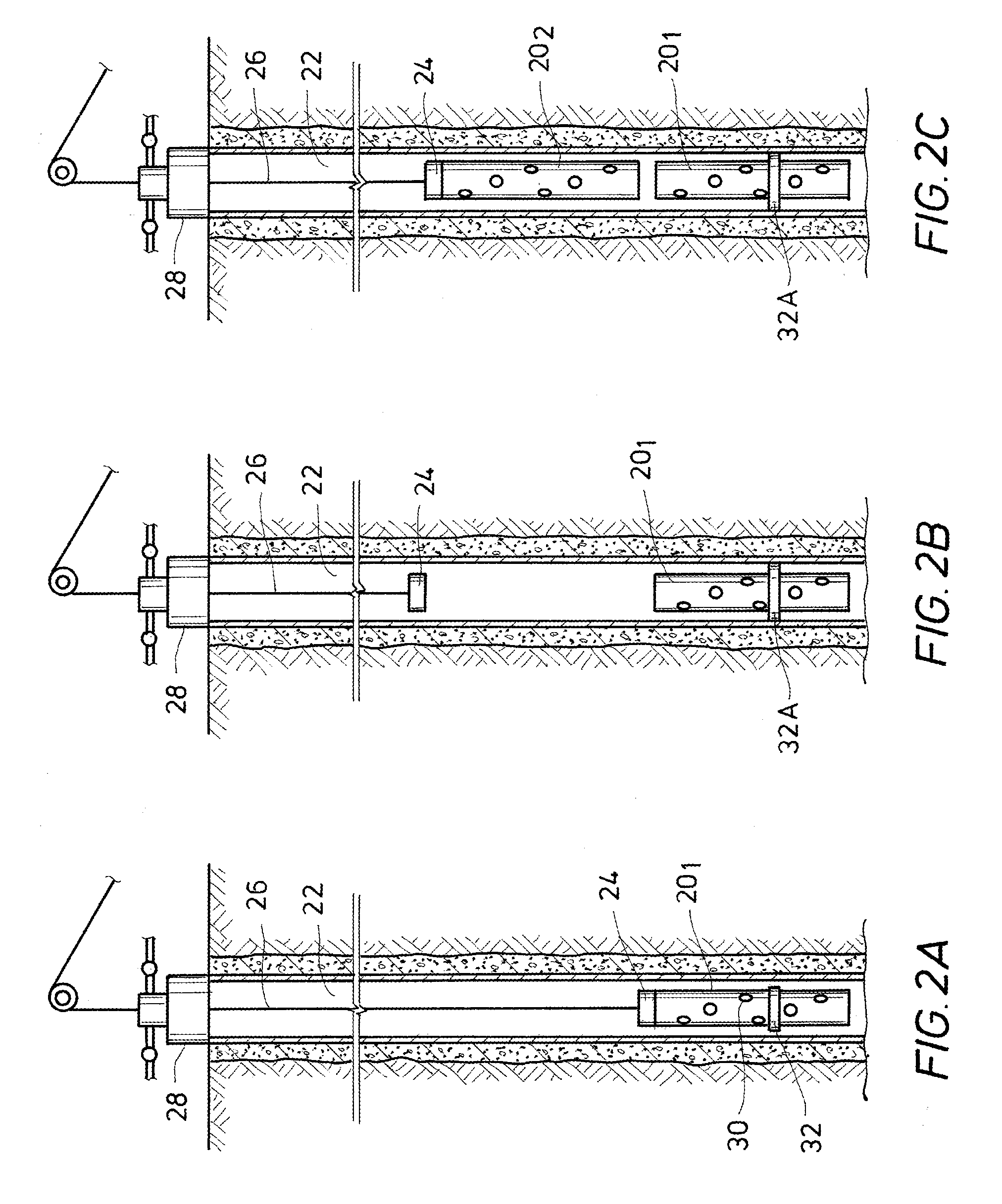
BACKGROUND[0001]1. Field of Invention[0002]The invention relates generally to the field of oil and gas production. More specifically, the present invention relates to a system and method for stacking perforating guns to form a perforating string.[0003]2. Description of Prior Art[0004]Perforating systems are used for the purpose, among others, of making hydraulic communication passages, called perforations, in wellbores drilled through earth formations so that predetermined zones of the earth formations can be hydraulically connected to the wellbore. Perforations are needed because wellbores are typically completed by coaxially inserting a pipe or casing into the wellbore. The casing is retained in the wellbore by pumping cement into the annular space between the wellbore and the casing. The cemented casing is provided in the wellbore for the specific purpose of hydraulically isolating from each other the various earth formations penetrated by the wellbore.[0005]Perforating systems t...

Claims


Application Information

Patent Timeline
Patent Type & Authority Applications(United States)
IPC IPC(8): E21B43/11
CPCE21B43/112E21B23/01
Inventor SAMPSON, TIM W.
Owner BAKER HUGHES INC
Why Eureka
Try Eureka