Perforating gun assembly and method for controlling wellbore pressure regimes during perforating

a perforating gun and perforating technology, applied in the direction of borehole/well accessories, nuclear explosives, nuclear engineering, etc., can solve the problems of affecting the productivity of formation and causing the perforation tunnel to fail

Active Publication Date: 2012-12-25
HALLIBURTON ENERGY SERVICES INC
View PDF56 Cites 44 Cited by
  • Summary
  • Abstract
  • Description
  • Claims
  • Application Information

AI Technical Summary

Benefits of technology

[0009]The present invention disclosed herein comprises an apparatus and method for perforating a cased wellbore that create effective perforation tunnels. The apparatus and method of the present invention also provide for safe installation and operation procedures as well as for the management of wellbore pressure regimes and the dynamic underbalance phenomena. Further, the apparatus and method of the present invention provide for managing the movement of the gun system and attached pipe or tubing, managing tension and compression in the conveyance tubing and managing the pressure differential applied to packers set in the wellbore above or below the perforating interval.
[0016]In a further aspect, the present invention is directed to a perforating gun assembly that includes shaped charges having cases that are surrounded by or are in close proximity to reactive materials. For example, the reactive material may be in the form of a sleeve or a coating disposed on the inner or outer surface of the carrier gun body. In another embodiment, the reactive materials may be nanoparticles that are applied, for example, as a nanolaminate that is disposed on various perforating gun components, such as charge cases, the charge loading tube, the interior or exterior of the carrier gun body or the like. Alternatively or additionally, the reactive materials, in either powder size or nanosize, may be blended into the explosive powder of the shaped charges to generate additional pressure to offset the dynamic underbalance.

Problems solved by technology

This inflow is beneficial as perforating generates debris from the perforating guns, the casing and the cement that may otherwise remain in the perforation tunnels and impair the productivity of the formation.
While creating a dynamic underbalance is beneficial in many circumstances, it has been found that there are some circumstances where excessive dynamic underbalance causes the perforation tunnel to fail due to, for example, sanding.

Method used


Image

  • Perforating gun assembly and method for controlling wellbore pressure regimes during perforating
  • Perforating gun assembly and method for controlling wellbore pressure regimes during perforating
  • Perforating gun assembly and method for controlling wellbore pressure regimes during perforating

Examples


Embodiment Construction

[0022]While the making and using of various embodiments of the present invention are discussed in detail below, it should be appreciated that the present invention provides many applicable inventive concepts which can be embodied in a wide variety of specific contexts. The specific embodiments discussed herein are merely illustrative of specific ways to make and use the invention, and do not delimit the scope of the present invention.

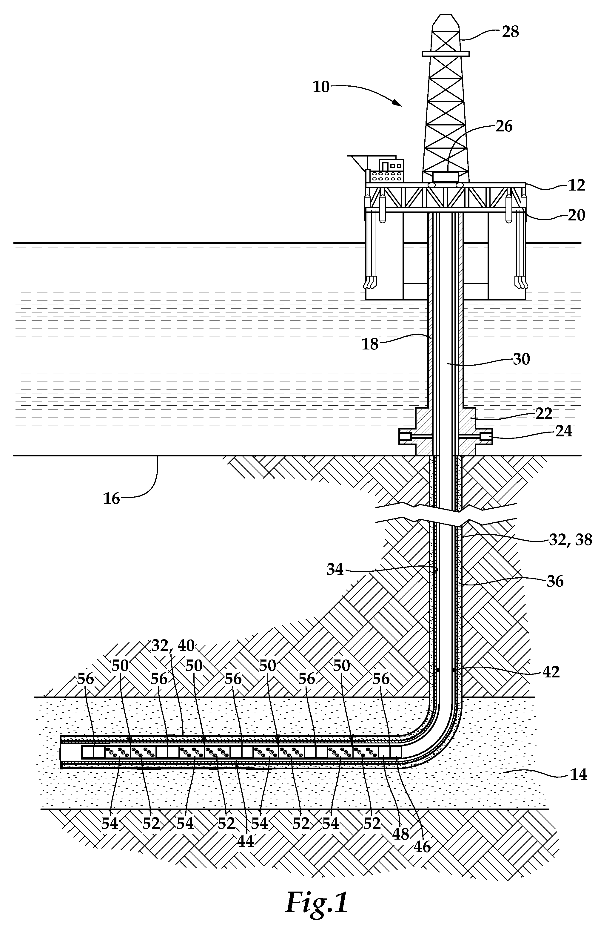
[0023]Referring initially to FIG. 1, a plurality of perforating gun assemblies of the present invention operating from an offshore oil and gas platform are schematically illustrated and generally designated 10. A semi-submersible platform 12 is centered over a submerged oil and gas formation 14 located below sea floor 16. A subsea conduit 18 extends from deck 20 of platform 12 to wellhead installation 22 including subsea blow-out preventers 24. Platform 12 has a hoisting apparatus 26 and a derrick 28 for raising and lowering pipe strings such as work st...


PUM


Abstract

A perforating gun assembly for use in a wellbore. The perforating gun assembly includes a carrier gun body and a charge holder disposed within the carrier gun body. A plurality of shaped charges are supported within the carrier gun body. A secondary pressure generator is operably associated with at least one of the shaped charges. The secondary pressure generator optimizes the wellbore pressure regime immediately after detonation of the shaped charges by controlling the dynamic underbalance created by the empty gun chambers to prevent excessive dynamic underbalance which may detrimentally effect the perforating operation.

Description

CROSS-REFERENCE TO RELATED APPLICATIONS[0001]This application claims benefit of U.S. Provisional Application No. 61 / 222,106, filed on Jul. 1, 2009.TECHNICAL FIELD OF THE INVENTION[0002]This invention relates, in general, to perforating a cased wellbore that traverses a subterranean formation and, in particular, to a perforating gun assembly that is operated to perforate the casing and to control the pressure condition in the wellbore during perforating.BACKGROUND OF THE INVENTION[0003]Without limiting the scope of the present invention, its background will be described with reference to perforating a subterranean formation using perforating gun, as an example.[0004]After drilling the various sections of a subterranean wellbore that traverses a formation, individual lengths of relatively large diameter metal tubulars are typically secured together to form a casing string that is positioned within the wellbore. This casing string increases the integrity of the wellbore and provides a ...

Claims


Application Information

Patent Timeline
Patent Type & Authority Patents(United States)
IPC IPC(8): E21B43/117
CPCE21B43/117E21B43/12
Inventor BARLOW, DARREN ROSSVAN LE, CAMBARKER, JAMES MARSHALL
Owner HALLIBURTON ENERGY SERVICES INC
Why Eureka
Try Eureka