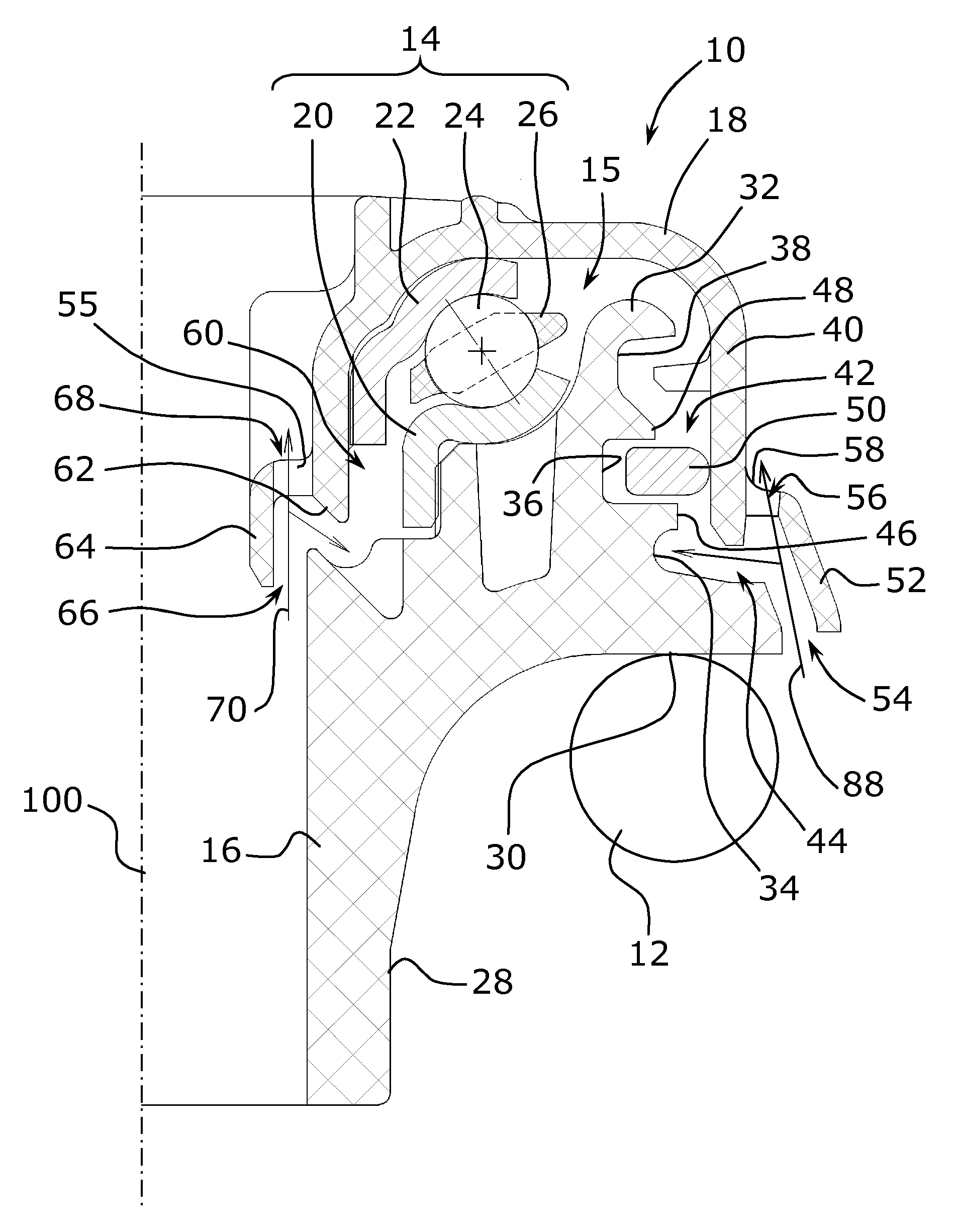
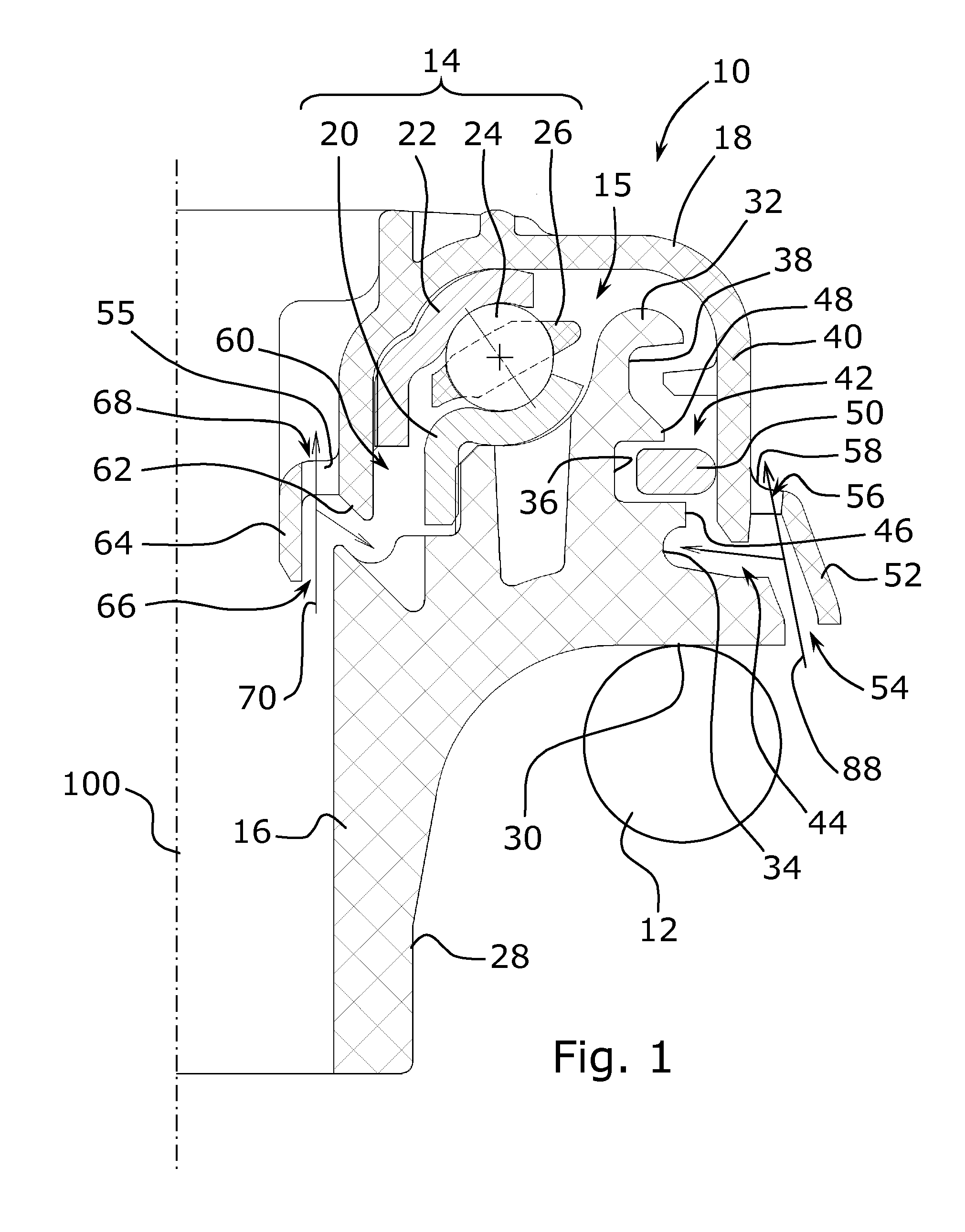
[0027]FIG. 1 shows a suspension stop device 10 intended to constitute a pivoting interface between a top turn of a coil spring 12 and the body of a vehicle. This stop device 10 comprises a bearing 14 providing the pivoting connection about an axis 100, this bearing 14 being housed in an annular cavity 15 between a bottom support piece 16 under which the top turn of the spring 12 will bear, and a protective cover 18. Where applicable, filtering blocks (not shown) can be provided between the top turn of the spring and the support piece, and/or above the cover. The cover 18 is conformed so as to be housed either directly in a cavity provided for this purpose in the body, or on an interface plate for fixing to the body. In the example considered, the bearing 14 is a roller bearing consisting of a bottom washer 20 and a top washer 22 forming rolling tracks for rolling bodies 24 that are moreover guided in a guide cage 26. The bottom washer 20 rests on reliefs on the bottom support piece 16 provided for this purpose, whereas the top washer is housed in the cover 18.
[0028]The support piece 16 comprises, on the side opposite to the bearing, a cylindrical skirt 28 for guiding the spring, and a transverse shoulder 30 supporting the spring 12. Between the shoulder 30 and the spring 12 the annular end of a concertina collar (not shown) can be interposed, intended for protecting the damper against external pollution, this end of the collar forming where applicable a mechanical filter between the spring and the bottom support piece 16, making it possible in particular to limit the transmission of noises from the running of the wheel to the body of the vehicle. The support piece 16 also comprises an annular wall 32 situated radially outside the bearing 14 and projecting towards the cover 18, this wall 32 having several annular grooves 34, 36, 38, here three in number, open radially towards the cover 18.
[0029]The cover 18 has an external skirt 40 disposed opposite this annular wall 32. The cover 18 and support piece 16 are arranged so as not to come into direct contact with each other and to form between them an annular passage in a labyrinth 42, taking advantage of the annular grooves 34, 36, 38 of the annular wall 32 of the support piece 16. In this example embodiment, the labyrinth 42 consists of an essentially radial annular entry portion 44 having a bottom formed by the annular groove 34, a second portion at the annular groove forming a chamber connected to the entry portion 44 by a narrow axial annular opening 46, and a third portion formed at the annular groove 38, connected to the second portion by a narrow annular opening 48.
[0030]A movable sealing gasket 50 is housed in the chamber 36 of the second portion. The gasket 50 is in sliding radial abutment against the skirt 40 of the cover and is sized so as to have, with the support piece 16, an axial and radial functional clearance. During high mechanical forces causing deformations or relative movements between the support piece 16 and the cover 18, the sealing gasket 50 is able to come into contact with a wall of the support piece 16, but this possible double sliding contact with the support piece 16 and the cover 18 generates only a low friction torque.
[0031]Moreover, the gasket 50 can be caused to move axially in order to close the passage 48 between the second and third portions, if it undergoes significant pressure.
[0032]The cover 18 is moreover provided with a deflector 52 that protects the entry portion 44 of the labyrinth. This deflector consists of an annular wall disposed radially outside and facing the entry portion 44, preventing direct access in a straight line to this entry portion 44. The wall of the deflector 52 is extended downwards opposite the support piece 16 in order to form with the support piece 16 an annular bottom opening 54 for access to the entry portion 44. It is also extended upwards opposite the skirt 40 of the cover in order to form with the skirt 40 of the cover top openings 56 for access to the entry portion 44. The top openings 56 are separated by bridges 58 of material connecting the deflector 52 to the skirt 40 of the cover, but the effective total cross-section of the top openings 56 remains high, greater than half of the effective cross-section of the bottom opening 54.
[0033]As illustrated in the figure, a ray of light 88 entering through the bottom opening 54 in the general direction of this opening emerges again through the top opening 56. It is thus ensured that, when a jet of pressurised water is oriented so as to enter the bottom opening 54, a large part of the flow emerges without being diverted through the top openings 56. The residual flow entering the entry portion 44 must fill the groove 34 before being able to rush into the passage 46 connecting with the second portion. If the flow is still very powerful at this level, it causes an axial movement of the gasket 50 parallel to the rotation axis of the bearing, the gasket thus closing the passage 48 to the third portion and to the bearing.
[0034]An external deflector 52 is described here, situated radially outside the thrust bearing 14, to protect the labyrinth 42, which can be termed external in the sense that it is situated radially outside the housing 15 of the stop bearing 14. The same principle is applicable for protecting the passage 60 existing between the cover 18 and the support piece 16 at the internal periphery of the stop. This is because this passage 60, also conformed as a labyrinth, can also in certain uses be sprayed by pressurised jets with a risk of penetration of water inside the housing 15 through an entry portion 62 situated radially inside the housing 15, that is to say between the housing 15 and the rotation axis 100. An internal deflector 64 is therefore provided, connected to the cover 18 by bridges 55 disposed opposite this entry portion so as to form two bottom 66 and top 68 openings constituting two passage channels from the outside in the entry portion 62. The top opening 68 is situated in line with the bottom opening 66, in the sense that it is possible to trace a light ray 70 entering through the bottom opening 66 and emerging through the top opening 68 without being diverted and without entering the entry portion 62.
[0035]Naturally, various variants are possible. The deflector may be attached to the cover or to the support piece. It may also be an integral part of the support piece.