
Suspension stop with reinforced sealing

a suspension stop and reinforced technology, applied in the direction of resilient suspensions, suspension arms with pivoted positions, bearings, etc., can solve the problems of drag torque, low sealing quality, sliding torque between rotating parts, etc., and achieve the effect of minimising the pressure rise in the entry portion

Inactive Publication Date: 2014-09-02
TORRINGTON COMPANY
View PDF21 Cites 0 Cited by
  • Summary
  • Abstract
  • Description
  • Claims
  • Application Information

AI Technical Summary

Benefits of technology

The patent describes a device that prevents water from entering the bearing of a suspension stop device. The device has two openings that are connected in parallel, with one opening serving as a diversion in case of a high-pressure spray. The device also has a labyrinth that minimizes pressure rise and allows water to flow through it without reflection or entering the entry portion. The entry portion of the labyrinth is connected to the bearing through an axial annular opening, which is delimited between the support piece and the cover. This design prevents water injection and ensures proper functioning of the suspension stop device.

Problems solved by technology

This technology has the disadvantage of causing a sliding torque between the rotating parts, referred to as drag torque, which is particularly detrimental in applications to steered wheels.
However, ingress of liquid by capillarity is not excluded and the seal is not of good quality.
However, new practices with regard to washing of vehicles and in particular washing the underside of the body by high-pressure water jet, shift the requirements with regard to protection of suspension stop bearings.

Method used


Image

  • Suspension stop with reinforced sealing
  • Suspension stop with reinforced sealing

Examples


Embodiment Construction

)

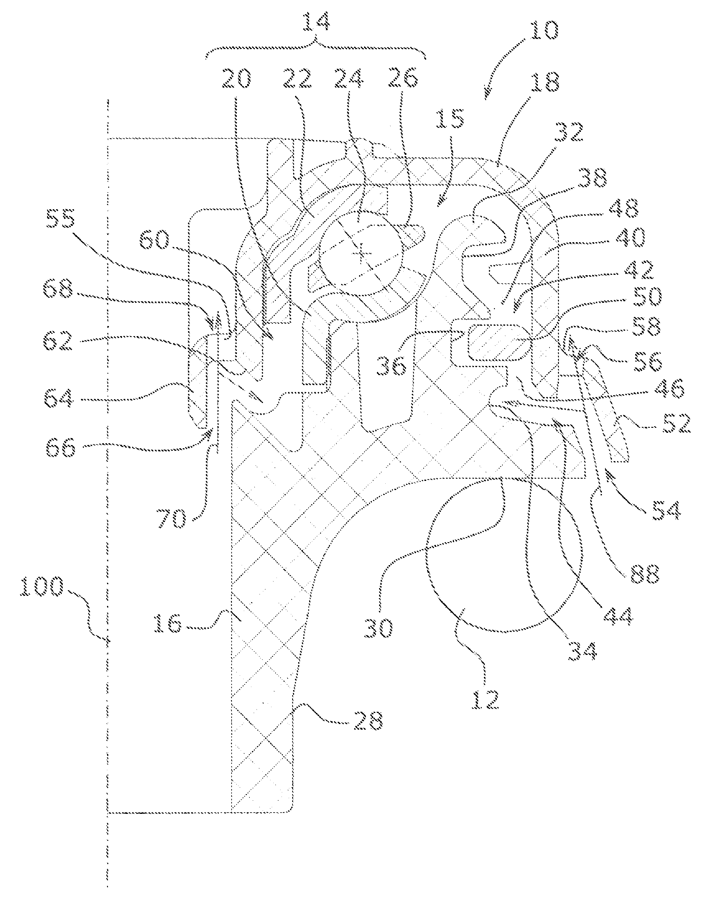
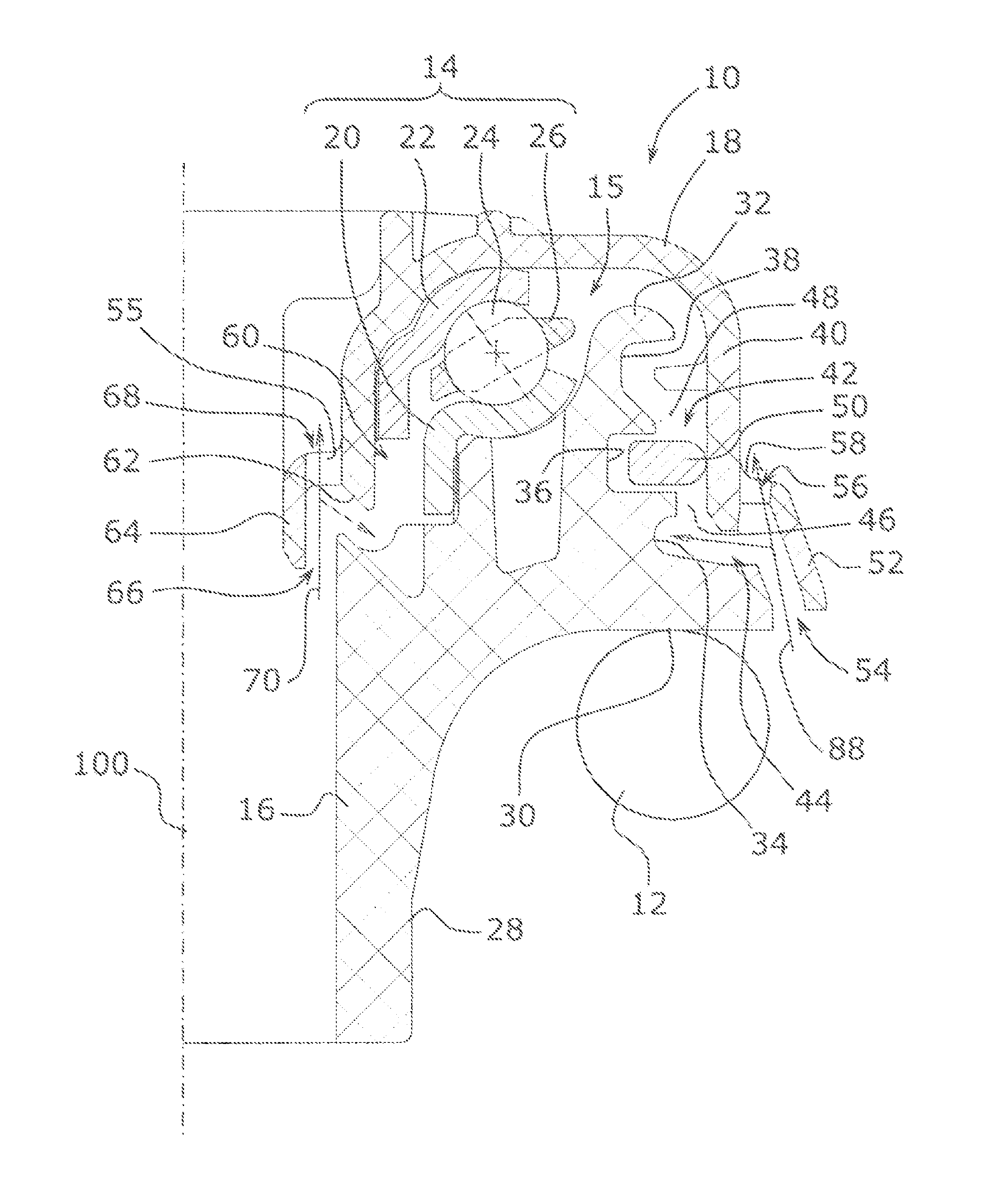
[0027]FIG. 1 shows a suspension stop device 10 intended to constitute a pivoting interface between a top turn of a coil spring 12 and the body of a vehicle. This stop device 10 comprises a bearing 14 providing the pivoting connection about an axis 100, this bearing 14 being housed in an annular cavity 15 between a bottom support piece 16 under which the top turn of the spring 12 will bear, and a protective cover 18. Where applicable, filtering blocks (not shown) can be provided between the top turn of the spring and the support piece, and / or above the cover. The cover 18 is conformed so as to be housed either directly in a cavity provided for this purpose in the body, or on an interface plate for fixing to the body. In the example considered, the bearing 14 is a roller bearing consisting of a bottom washer 20 and a top washer 22 forming rolling tracks for rolling bodies 24 that are moreover guided in a guide cage 26. The bottom washer 20 rests on reliefs on the bottom support piece...


PUM


Abstract

A suspension stop device for a suspension arm of a vehicle, having a coil spring, having a stop bearing defining a rotation axis of the device and a bottom metal washer turning with respect to a top metal washer; a support piece for transmitting to the bottom washer forces exerted by the spring, the support piece comprising a support zone for the bottom washer; a cover covering the top washer and delimiting with the support piece a housing for the bearing, the cover being provided with a skirt covering a peripheral zone of the support piece and delimiting with the peripheral zone of the support piece an annular labyrinth, disposed radially outside the housing and connecting the housing to the outside; and an annular deflector delimiting with the skirt of the cover at least one top opening and with the support piece at least one bottom opening.

Description

BACKGROUND[0001]1. Technical Field of the Invention[0002]The invention relates to a suspension stop for a vehicle suspension arm, in particular for a telescopic suspension arm of a motor vehicle steered wheel, provided with a bearing and means of protecting this bearing.[0003]2. Prior Art[0004]Traditionally, suspension stop bearings are housed in casings in two parts, closed by sealing lips fixed to one of the parts of the casing and sliding over the other part of the casing, as illustrated in the document EP 1 000 781. This technology has the disadvantage of causing a sliding torque between the rotating parts, referred to as drag torque, which is particularly detrimental in applications to steered wheels.[0005]To eliminate this drag torque, it has been proposed to replace the traditional sealing linings with contactless chicane devices, that is to say devices in which the rotating elements are interleaved in one another, without contact, so as to create a significant pressure drop ...

Claims


Application Information

Patent Timeline
Patent Type & Authority Patents(United States)
IPC IPC(8): F16C19/10F16C33/76F16C33/80
CPCB60G15/068B60G2204/418F16C19/10F16C27/04F16C33/761F16C33/7886F16C33/80F16C2361/53F16C2326/05B60G7/02B60G15/06F16C33/76
Inventor CHAMOUSSET, ANTHONY
Owner TORRINGTON COMPANY
Features
  • Generate Ideas
  • Intellectual Property
  • Life Sciences
  • Materials
  • Tech Scout
  • Unparalleled Data Quality
  • Higher Quality Content
  • 60% Fewer Hallucinations
Learn More