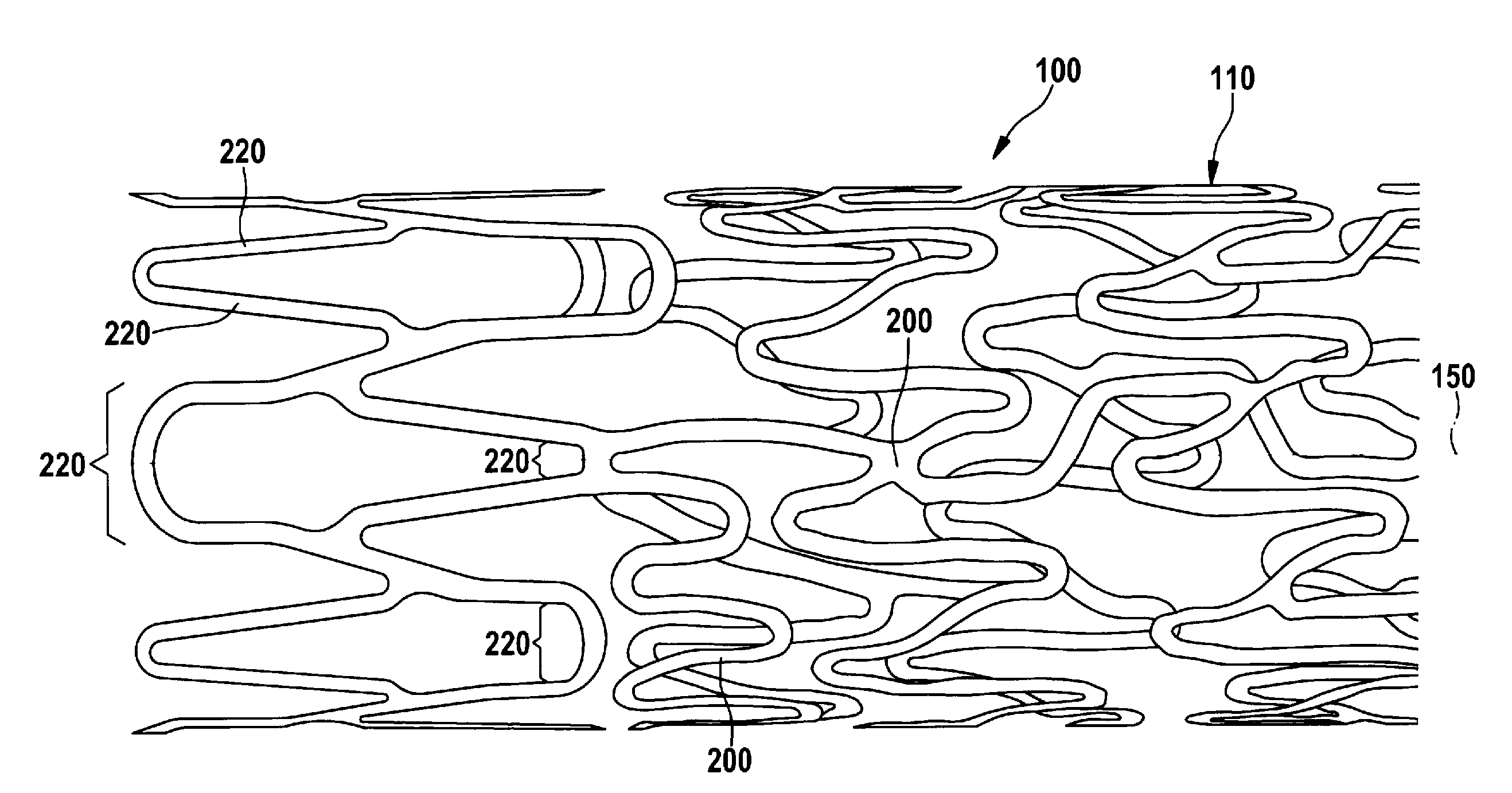
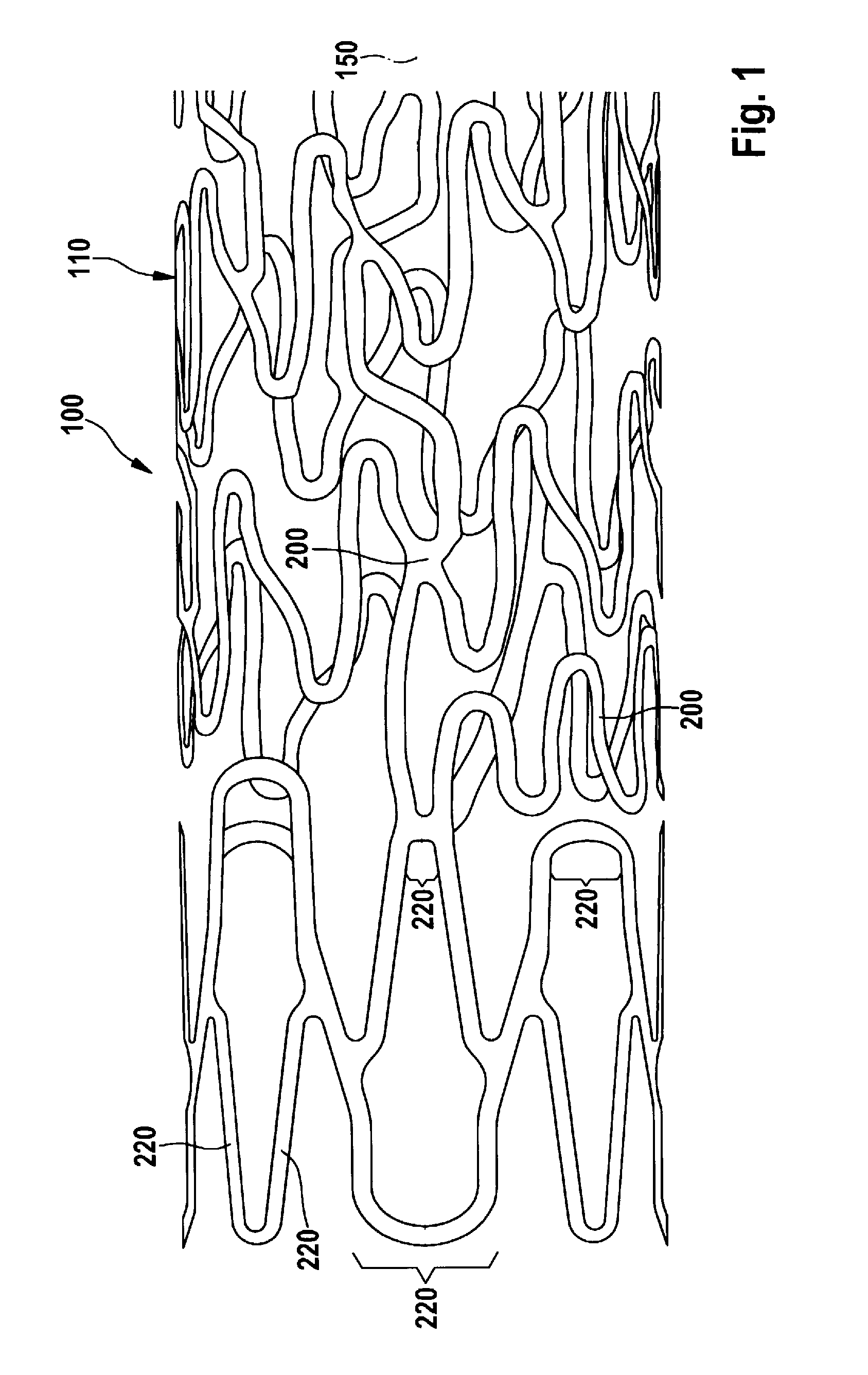
[0011]According to the invention, a stent is provided that has a tubular, individual-struts-comprising lattice structure, wherein the stent has at least one strut, of which at least one longitudinal section runs with at least one directional component in the radial circumferential direction of the stent, and wherein the radially outward-facing (mural) surface of the longitudinal section of the strut is curved only around one longitudinal axis of the stent. According to the invention, the surface of the strut's longitudinal section (luminal) facing towards the inside of the stent has a curvature such that the cross section of the strut is fluidically optimized. The invention thus relates to the design of a strut, or also only of a longitudinal section of a strut, that runs with at least one directional component in a radial circumferential direction of the stent. This means that the strut, or its longitudinal section, runs parallel to a tangent applied to the circumference of the stent, or has one component that is oriented in this direction. What is excluded according to the invention, however, are the longitudinal strut sections that run only parallel to the longitudinal axis of the stent. This fundamentally distinguishes the stent according to the invention from the embodiments shown in EP 0 824 903 A1. These types of struts according to the invention can be easily
cut from a tube by
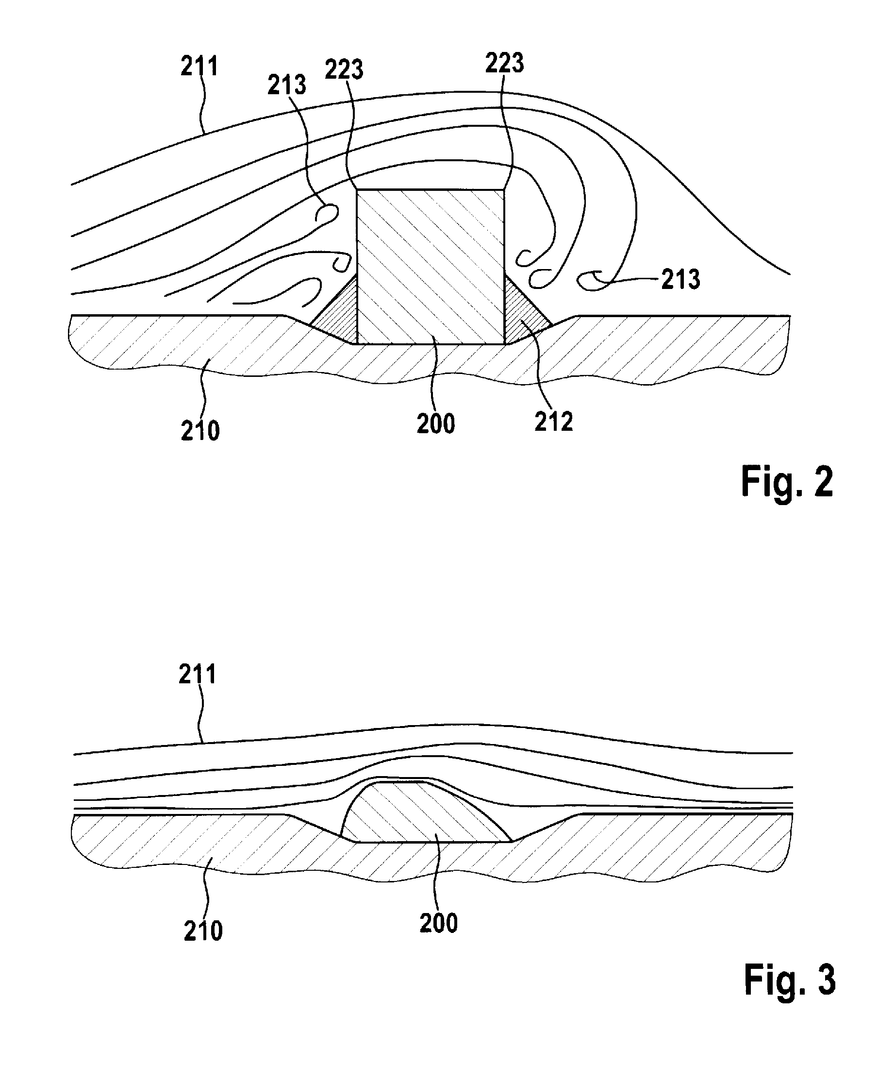
laser. What is understood by the strut cross section is that cross section which is produced by a section in the longitudinal axis of the stent through the longitudinal section of the strut with one directional component in the radial circumferential direction, in other words, performed in the direction of the longitudinal axis of the stent. According to the invention, the strut in cross section has only on the luminal surface in its longitudinal direction a curvature which is designed to prevent turbulences of the
blood flow passing through the stent, and thus prevent deposits. On the mural side, the strut has no curvature in the cross section running in the longitudinal direction of the stent. This design is particularly advantageous since the mural contact surface of the strut on the
vascular wall is not thereby reduced, and thus the pressure of the strut on the
vascular wall is limited, thereby reducing the risk of damage to the vessel.
[0013]In a preferred embodiment of the stent according to the invention, provision is made whereby the stent's inward-facing curvature of the strut's surface is designed to be asymmetrically convex. This means that as viewed in cross section the curvature of the luminal surface can have at every point a different distance from the mural surface of the strut section, where the convex curvature is of asymmetric shape. In other words, the curvature of the luminal surface, as viewed in cross section, has different convex regions that determine the
asymmetry. The
asymmetry in the convex shape produces a streamlined design of the strut cross section, as a result of which the
blood flow passing through the stent flows laminarly in the region of the strut and deposits on the strut are prevented. It is specifically this laminar flow motion of the blood effected by the cross section that has the additional very important effect of promoting the endothelialization of the stent, which is the “in-growth” with the endothelial cells. This too results in the prevention of deposits.
[0020]In a first alternative embodiment of the invention, provision is made whereby all of the strut sections of the stent that run with one directional component perpendicular to the longitudinal direction of the stent are designed in accordance with the present invention. As a result, the embodiment of the strut according to the invention is not restricted to specific sections of the stent; instead, all struts of those stents in general can be designed according to the invention which has a directional component perpendicular to the longitudinal direction of the stent. In a second alternative embodiment, the stent has struts that are designed according to the invention only at its end regions, where the end regions, starting from one stent end each, each extend over 20 to 30 percent of the length of the stent. This means that the struts are designed in a fluidically optimized fashion only at the end regions of the stent. The center region of the stent—aside from the conventional
electropolishing, which continues to be employed, used to smooth the strut surfaces and to preclude sharp strut edges—thus does not undergo any surface treatment of the strut that significantly modifies the strut cross section. This may be sufficient for simple stents since experience shows that the deposits occur only at the end regions of the sent (usually at the proximal end of the stent) and not at the center of the stent. This embodiment has the
advantage that the wall thickness of the stent, that is, the material thickness of the strut in the center region of the stent, is of thicker design than at least at the proximal stent end. It is also possible to implement the stent such that a surface treatment of varying degree is performed over the length of the stent, thereby making the cross-sectional area of the strut larger as the strut 30 becomes more centrally located in the stent. This means that the removal of material so as to effect the fluidic optimization of the strut cross section becomes greater the further away a strut is located at the end of the stent. This in turn has the
advantage that the wall thickness is made thickest specifically in that region of the stent in which the greatest bending stress is found when a
bending moment is applied to the stent end. As a result, the stent ends here remain flexible and can thus more easily adapt to movements of tissue. Another
advantage is that the transition between region in which the vascular wall is supported by a stent of this design and the vascular wall immediately adjacent to the stent ends is “soft.” This means that the elasticity of the vessel increases or decreases nonincrementally. In other words, an abrupt drop in elasticity between unsupported tissue wall and vascular wall is prevented. This minimizes
mechanical irritation at the stent ends and in turn lowers the risk of focal stenoses at the stent ends.
[0024]Another aspect of the present invention is the use of the stent according to the invention as an
implant in a vessel to prevent vascular construction. The stent according to the invention thus relates to an embodiment that is fabricated such that it already has the fluidically-optimized curved surface on the luminal side of the strut during implantation. This distinguishes the stent according to the invention from embodiments in which a strut cross section that is at least partially adapted to the
blood flow does not result until after relatively long implantation of the stent due to
material erosion of the strut. By using the stent according to the invention, it is thus possible to prevent deposits immediately after implantation.
[0026]The lattice structure is generated in the conventional fashion by
laser cutting of the tube. The particles of the
particle beam here can comprise fine-grained sand or spherical
pellets composed of a
solid material. Due to scattering of the
particle beam, the beam also strikes edges that are not located directly within the projection range of a
nozzle from which the
particle beam emerges. The slight tumbling motion or gyrating motion of the particle beam ensures that the particles strike to a sufficient degree all strut edges located in front of the
nozzle within the range of the beam. This thus enables a
rounding to be produced of the luminal edges of the strut such that these edges have the fluidically optimized cross section according to the invention.
[0034]The stent according to the invention can thus be rounded at its luminal edges by means of the method according to the invention and associated device such that the blood flow passes laminarly along the struts designed according to the invention. The mural edges here are not rounded beyond what is achievable by standard
electropolishing so as to keep the mural
support surface as large as possible and thereby minimize the pressure on the vascular wall in order to prevent injury. The asymmetrical cross-sectional shape of the strut is fluidically optimized, wherein this can be designed according to fluidic
simulation models. For example, an asymmetrical
rounding of the luminal edges can be effected at the stent end regions, wherein in particular the proximal end of the stent is fluidically optimized. As a result, the formation of deposits along the strut is prevented and the risk of unwanted neointimal hyperlasias and arteriosclerotic phenomena is reduced. Due to the fact that the removal of material occurs preferentially at the stent end regions, the wall thickness of the support structure is reduced only in these stent end regions. This means that the center region of the stent has a wall thickness of the support structure that matches the wall thickness of the tube from which the support structure has been
cut out. The result is a reduced flexural stiffness at the stent ends and a by comparison increased flexural stiffness at the stent center. These properties are advantageous in particular in the event the stent when in use must follow motions of the vessel in which it has been inserted. This means that the stent designed according to the invention can more easily participate in the motion of the vessel, thereby avoiding breaks or gaps between the stent end and the vascular wall resting thereon, with the result that the risk of deposits' forming in this region is reduced.

