System and method for accurately directing antennas

a technology of accurate directing and antennas, applied in the field of directional antennas, can solve the problems of weak signal transmission and reception, affecting the quality of information that is being transferred, and the accuracy of antenna alignment, so as to achieve accurate and time-efficient redirection

Inactive Publication Date: 2012-12-20
BRUCHIEL TOMER
View PDF10 Cites 15 Cited by
  • Summary
  • Abstract
  • Description
  • Claims
  • Application Information

AI Technical Summary

Benefits of technology

[0024]Optionally, the rotation sensor (such as a potentiometer for example) is permanently attached to the antenna, and is calibrated to the antenna's initial azimuth and afterwards used to provide continuous indication of its updated azimuth. Knowledge of the antenna's azimuth enables its accurate and time-efficient redirection at any time and without the need to perform any further measurements.

Problems solved by technology

It is well known in the field of directional antennas, such as for example cellular communication antennas, that imprecise alignment of the antenna leads to weaker signal transmission and reception to and from the required sector by the antenna and a generally smaller coverage range.
This affects the quality of the information that is being transferred, especially by 3-G cellular devices.
For example, this causes lower data transfer rates and more errors and interference.
For cellular companies, for example, this generally results in increased operational costs and loss of incomes.
The antenna can become misaligned with the predetermined direction in which it is supposed to point due to initial inaccurate alignment, lack of accurate direction measurements during realignment to the same or a different direction, and due to multiple gradual or sudden external factors such as wind, rain and intentional or unintentional actions of people in its vicinity.
However, the above and other prior art systems suffer from a number of disadvantages:1. As is well known, the direction of the Earth's magnetic North is not identical to the direction of the true North (which corresponds to the Earth's rotational axis).
This introduces an inherent error into the alignment process, which is further difficult to correct because the Earth's magnetic field is non-uniform and its direction can vary by many degrees at different locations on the Earth's surface.2. The common practice of using compasses is further problematic due to the potentially strong electromagnetic fields near antenna towers and could deteriorate the reading of a compass.
Today, for cellular networks for example, the initially inaccurate parameters are manually fed into the computer, which causes faults and lack of live, or at least daily, updates.
In time, this situation leads to considerable discrepancies between the computer records and the actual antenna pointing directions in field, thus making it nearly impossible for a communication or cellular engineer to optimally design the communication network, and might require extra redundancy in the form of more antenna towers for example, resulting in higher costs.4. Inaccuracies in the pointing directions of antennas in the field are likely to lead to poor reception and transmission coverage.
Poor coverage leads not only to interference, but also to reduced data transfer rates and errors.
This further translates into higher operating costs and loss of incomes for communications and cellular companies and the end-users.5. Due to environmental issues related to the electromagnetic radiation emitted by the antennas, especially in the more concentrated form for directional antennas, such as cellular antennas, every field deployed antenna receives a separate permit for its installation and operation.
Inherent inaccuracies in an antennas pointing direction reduce the range of possible installation sites and locations, and pointing direction inaccuracies during operation of an antenna can affect its permit and cause general legal problems to the transmission site and / or communication companies.6. Solutions involving mounting complex systems proximate to antenna / s that can find its azimuth are usually impractical and involve very high costs and other complications.

Method used


Image

  • System and method for accurately directing antennas
  • System and method for accurately directing antennas
  • System and method for accurately directing antennas

Examples


Embodiment Construction

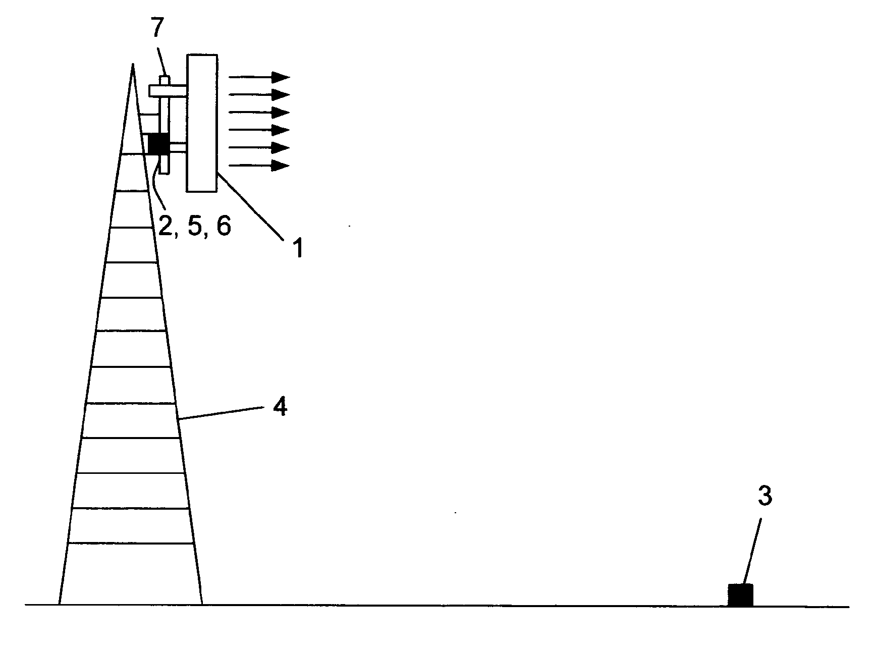
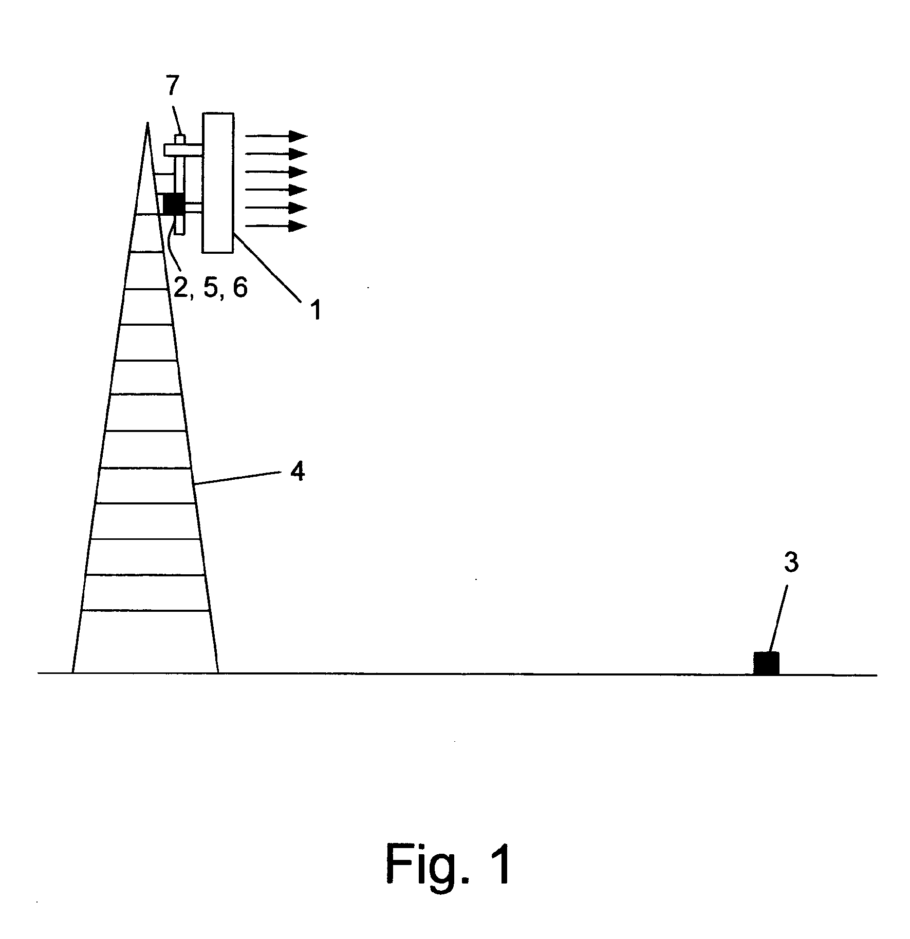
[0061]FIG. 1 schematically illustrates an embodiment of the present invention. A directional antenna 1 is pivotally attached to a vertical axle 7 which is mounted on an antenna tower 4. Antenna 1 has its primary transmission direction marked by the corresponding arrows. FIG. 1 illustrates an initial state when the system is used to carry out the initial calibration. A first GPS receiver 2 is positioned adjacent to antenna 1 as well as optical means 6, and a second GPS receiver 3 is positioned at a distance from antenna tower 4. Rotation sensor 5 is attached to antenna 1.

[0062]Optionally, rotation sensor 5 is intended to remain attached to antenna 1 for the duration of the operational life of antenna 1, barring possible faults. For such a case, there is a possibility that antenna 1 is originally manufactured to include some of the system's components, at least including rotation sensor 5.

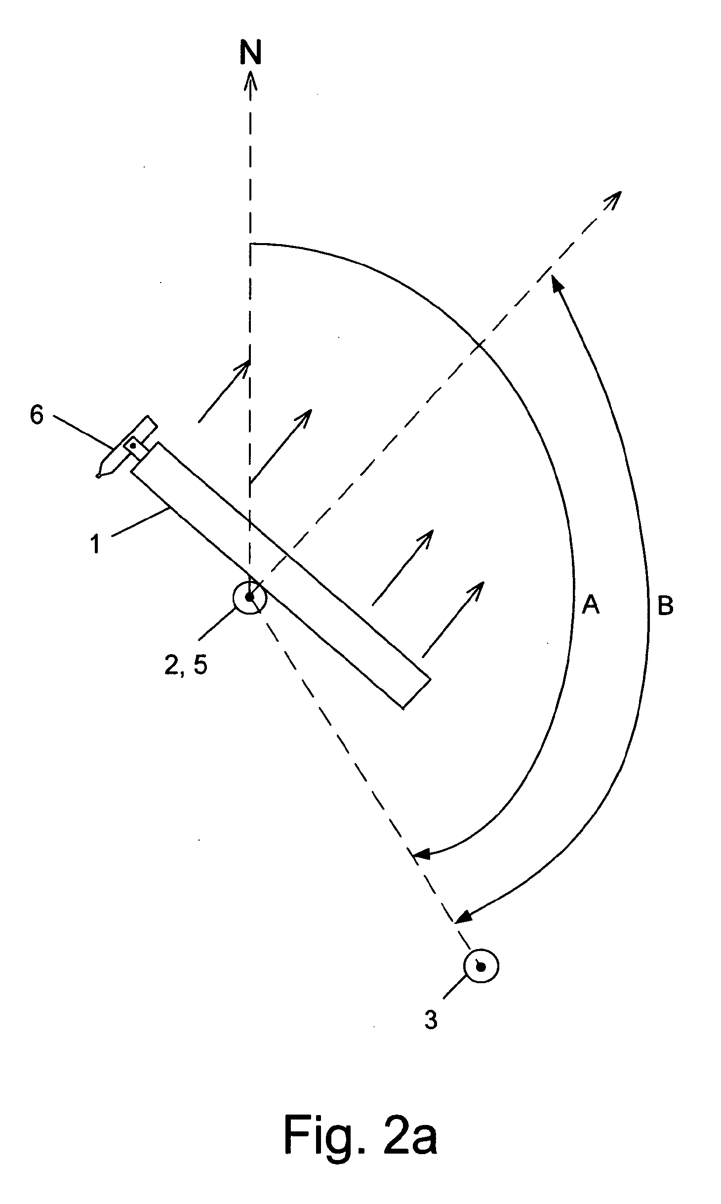
[0063]To perform initial direction of the antenna 1 to a predetermined azimuth, the azimuth must ...


PUM


Abstract

A system for accurately directing a directional antenna, that includes a calibration system for finding the current azimuth of the antenna and a rotation sensor attached to the antenna, for measuring deviations from the current azimuth of the antenna. The calibration system includes a first GPS receiver located at the antenna's position; a second GPS receiver located adjacent to a visible object at a minimal distance from the antenna and in an arbitrary direction with respect to the first GPS receiver; rotatable optical means positioned adjacent to the antenna in an initial direction being parallel to the current direction of the antenna, the optical means being coupled to a meter for measuring the angle between the current direction and the direction to the visible object by rotating the optical means until seeing the visible object and means for calculating a first azimuth from the position of the first GPS receiver to the position of the second GPS receiver and the current azimuth of the antenna by subtracting the angle from the first azimuth.

Description

FIELD OF THE INVENTION[0001]The present invention belongs to the field of directional antennas. More particularly, the invention relates to a method for the alignment of a directional antenna to a predetermined azimuth.BACKGROUND OF THE INVENTION[0002]It is well known in the field of directional antennas, such as for example cellular communication antennas, that imprecise alignment of the antenna leads to weaker signal transmission and reception to and from the required sector by the antenna and a generally smaller coverage range. This affects the quality of the information that is being transferred, especially by 3-G cellular devices. For example, this causes lower data transfer rates and more errors and interference. For cellular companies, for example, this generally results in increased operational costs and loss of incomes. The antenna can become misaligned with the predetermined direction in which it is supposed to point due to initial inaccurate alignment, lack of accurate di...

Claims


Application Information

Patent Timeline
Patent Type & Authority Applications(United States)
IPC IPC(8): G01S19/53
CPCH01Q1/125H01Q3/04H01Q3/08G01S19/53
Inventor BRUCHIEL, TOMER
Owner BRUCHIEL TOMER
Why Eureka
Try Eureka