Information processing apparatus, information processing method, and program

a technology of information processing and information processing method, applied in the direction of program control, instruments, testing/monitoring control systems, etc., can solve the problem of dangerous spots in the area below the hanging load

Active Publication Date: 2012-12-20
NSSOL
View PDF4 Cites 63 Cited by
  • Summary
  • Abstract
  • Description
  • Claims
  • Application Information

AI Technical Summary

Benefits of technology

[0023]According to aspects presented herein, the operating status of a facility or the like can be communicated in a realistic manner to an observer in an installation or a factory.
[0024]Further, according to aspects presented herein, a dangerous spot can be indicated more appropriately when the dangerous spot changes temporally.

Problems solved by technology

There may be cases where a dangerous area is always dangerous, and there may be cases where it is dangerous only during a particular period of time.
For example, crane operation site in a factory, the area below a hanging load becomes a dangerous spot only when the crane is in operation.

Method used


Image

  • Information processing apparatus, information processing method, and program
  • Information processing apparatus, information processing method, and program
  • Information processing apparatus, information processing method, and program

Examples


embodiment 1

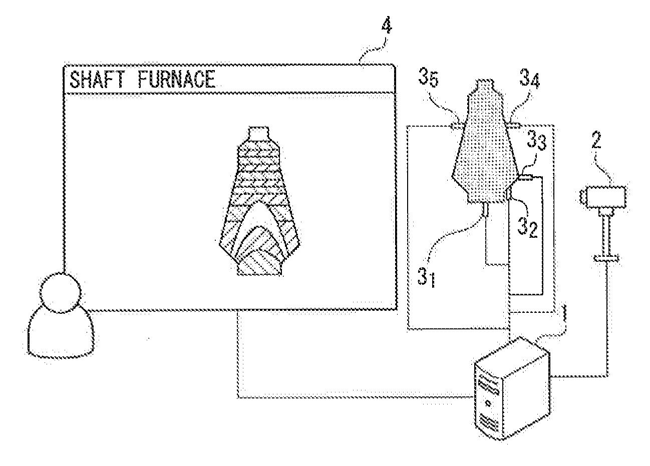
[0074]FIG. 1 is a diagram illustrating an example of a system structure of a facility guidance system of Embodiment 1. As illustrated in FIG. 1, in the facility guidance system, an AR (Augmented Reality) server 1, a camera 2, sensors 31 to 35, and a display device 4 are connected via a network.

[0075]To the AR server 1, an image of a facility in a factory (a shaft furnace in the example of FIG. 1) imaged by the camera 2 is input from the camera 2. Note that in the following embodiments including this embodiment, the description will be given taking examples of facilities in a steel plant as examples of facilities in a factory. Note that this will not limit the following embodiments including this embodiment.

[0076]Further, to the AR server 1, measurement information (for example, temperature information of the inside of the shaft furnace, or the like) measured by the sensors 31 to 35 is input from the sensors 31 to 35. Although five sensors are illustrated in FIG. 1, any number of sen...

embodiment 2

[0102]FIG. 8 is a diagram illustrating a system structure of a facility guidance system of Embodiment 2. As illustrated in FIG. 8, the system structure of the facility guidance system of Embodiment 2 newly includes an operation server 5 compared to the system structure of the facility guidance system of Embodiment 1.

[0103]The operation server 5 transmits control information to a facility inside a factory. The facility executes processing based on the control information. For example, when the facility is a shaft furnace, the operation server 5 transmits to the shaft furnace charging instruction information of sintered ore or the like for instructing charging of sintered ore or the like, cokes charging instruction information for instructing charging of cokes as an example of material, blowing instruction information of reducing agent for instructing blowing in of a reducing agent, tapping instruction information for instructing tapping from a tap hole, or the like.

[0104]Note that th...

embodiment 3

[0122]Depending on the factory, facilities may be in operation throughout the year, or there may be cases where facilities are not in operation for maintenance, cleaning, or the like. In this embodiment, there will be described a method for communicating, even when a facility is not in operation, the operating status of the facility or the like in a realistic manner to an observer in an installation or a factory. Note that a system structure, a software structure, and so on in this embodiment are similar to those of Embodiment 1 unless otherwise noted.

[0123]The creation unit 23 of this embodiment determines whether the facility is in operation or not based on the measurement information input from the measurement information input unit 22, and creates a virtual image based on the measurement information when it determines that the facility is in operation, or obtains from the storage device 12 or the like a virtual image generated in advance based on logical values or average values...


PUM


Abstract

An information processing apparatus including an imaged image input unit inputting an imaged image of a facility imaged in an imaging device to a display control unit, a measurement information input unit inputting measurement information measured by a sensor provided in the facility from the sensor to a creation unit, a creation unit creating a virtual image representing a status of an outside or inside of the facility based on the measurement information input by the measurement information input unit, and a display control unit overlaying and displaying the virtual image created in the creation unit and the imaged image input by the imaged image input unit on a display device.

Description

CROSS-REFERENCE TO RELATED APPLICATIONS[0001]This application is a Continuation of U.S. application Ser. No. 13 / 542,937, titled “Information Processing Apparatus, Information Processing Method, and Program, filed on Jul. 6, 2012, which is a Continuation of International Application No. PCT / JP2011 / 057769, with an international filing date of Mar. 29, 2011, which designates the United States of America, which claims priority to Japanese Application No. 2010-079219, filed on Mar. 30, 2010, Japanese Application No. 2010-138517, filed on Jun. 17, 2010, Japanese Application No. 2011-061339, filed on Mar. 18, 2011, and Japanese Application No. 2011-066594, filed on Mar. 24, 2011, the entire contents of each of which are incorporated herein by reference in their entirety.TECHNICAL FIELD[0002]The present invention relates to an information processing apparatus, an information processing method, and a program.BACKGROUND ART[0003]Conventionally, in an observation trip regarding an installation...

Claims


Application Information

Patent Timeline
Patent Type & Authority Applications(United States)
IPC IPC(8): G09G5/00G06F3/0481
CPCG05B23/0216G05B2219/32014G06F3/011G06F3/0481G06T19/006
Inventor IHARA, NOBORUSASAO, KAZUHIROYOKOYAMA, MASARUSAKURAI, ARATAOKAMOTO, RICARDO MUSASHI
Owner NSSOL
Why Eureka
Try Eureka