Eureka AIR delivers breakthrough ideas for toughest innovation challenges, trusted by R&D personnel around the world.

Rotary Input Device and Electronic Equipment

a rotary input device and input device technology, applied in the direction of instruments, computing, electric digital data processing, etc., can solve the problems of inability to give an operator any operating feelings, no sensible signals capable of an operator, and difficulty for an operator to recognize the selection of a selection item on the screen

Inactive Publication Date: 2010-10-28
FUKOKU CO LTD
View PDF20 Cites 0 Cited by
  • Summary
  • Abstract
  • Description
  • Claims
  • Application Information

AI Technical Summary

Benefits of technology

[0146]According to the present invention, when a predetermined pressure in an axial direction is applied to a rotary operation device, a rotary force is applied to the rotary operation device, and a force sense is presented to an operator operating the rotary operation device. Consequently, a more real operating feeling to a depression operation of the rotary operation device is realized, and the operator can surely perceive the input of a depression operation.

Problems solved by technology

Because each selection item on the screen of such a rotary input device is switched to be selected only by a rotation operation of the rotary operation device thereof, such a rotary input device has the problem that it is difficult for an operator to recognize the selection of a selection item on the screen as a sense of a hand or a finger of the operator.
The technique disclosed in Japanese Patent Application Laid-Open Publication No. 2003-228455, however, cannot give an operator any operating feelings at the time of depressing the jog dial, although the technique can give the operating feeling of the jog dial variability at the time of rotating it to transit the selection item from a certain one to the next one.
Moreover, also the technique disclosed in Japanese Patent Application Laid-Open Publication No. 2003-345499 cannot similarly give an operator any operating feelings at the time of depressing the dial, although the technique can enable the operator thereof to perceive the difference in the operation processing of a rotation operation of the dial by the operation feeling of the dial.
That is, both the techniques disclosed in Japanese Patent Application Laid-Open Publications Nos. 2003-228455 and 2003-345499 have no sensible signals capable of an operator to judge whether an input by a depression operation of a rotary operation device has surely been performed or not.

Method used


Image

  • Rotary Input Device and Electronic Equipment
  • Rotary Input Device and Electronic Equipment
  • Rotary Input Device and Electronic Equipment

Examples


Embodiment Construction

[0023]In the following, an embodiment of the present invention will be described in detail by reference to the accompanying drawings. Incidentally, the scope of the present invention is not limited to the shown examples.

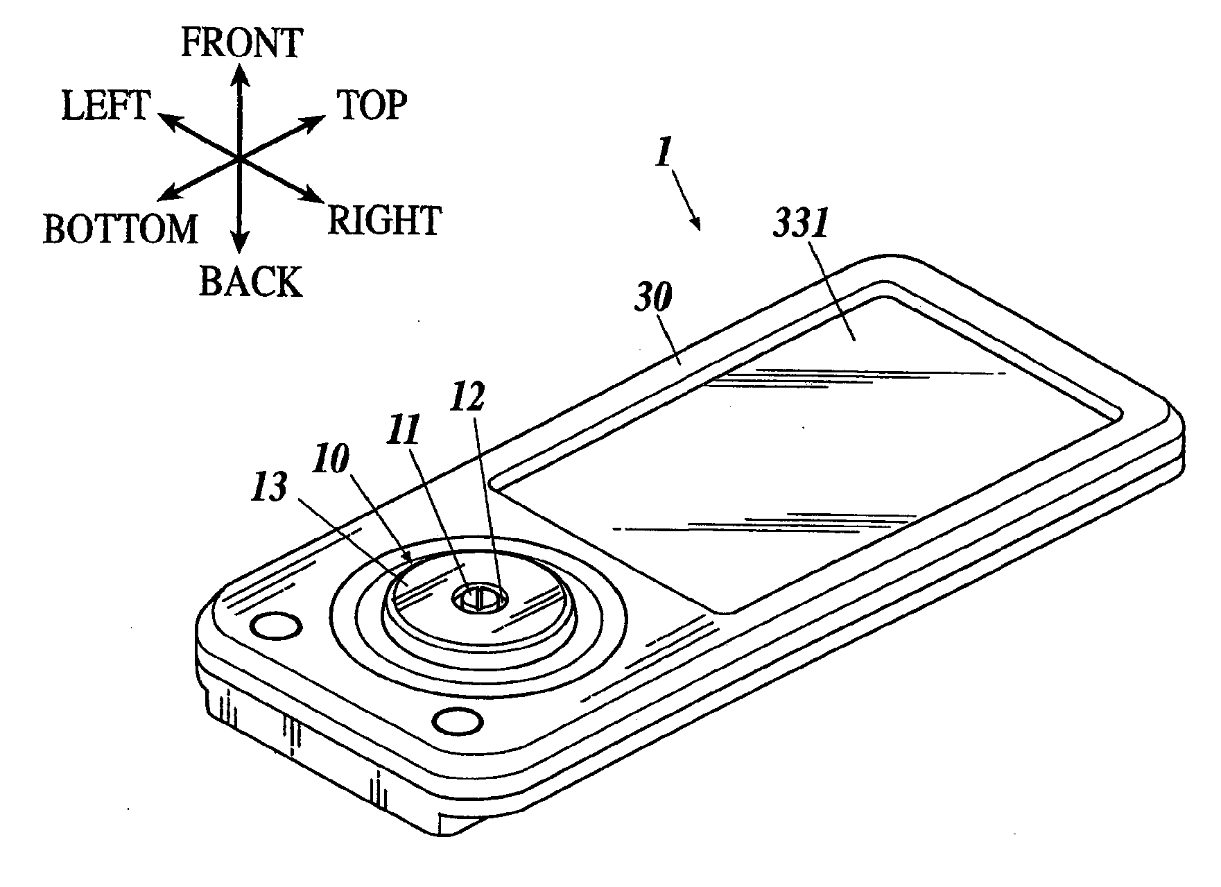
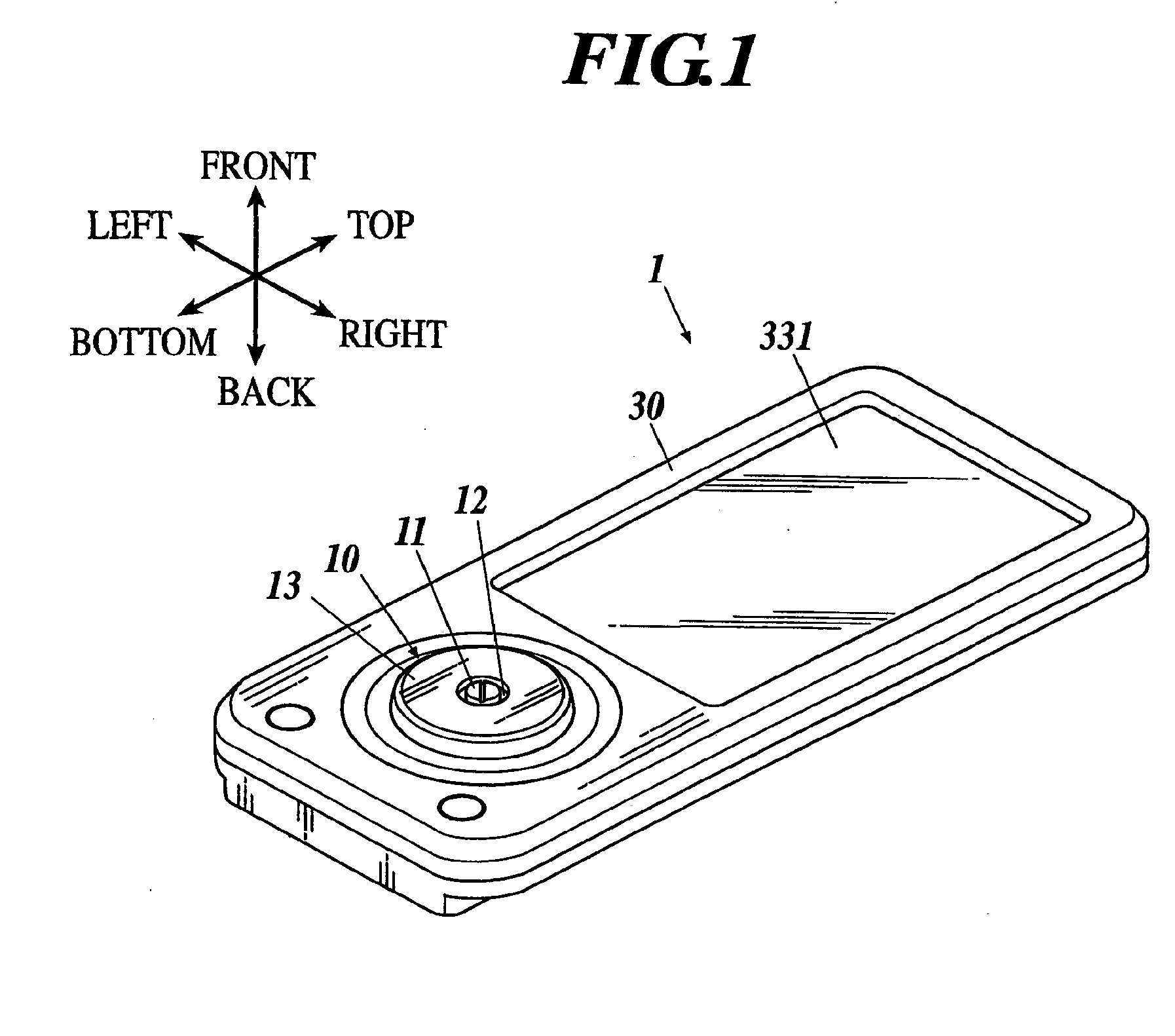
[0024]In the present embodiment, it is intended to describe the present embodiment by illustrating a cellular phone handset performing verbal communication by wireless communication as electronic equipment equipped with a rotary input device according to the present invention.

[0025]Incidentally, in the following description, it is supposed that the side on which a rotary input device 10 and a display panel 331 of a display section 33 are arranged is treated as the front side, and the side opposed to the side on which the rotary input device 10 and the display panel 331 are arrange is treated as the back side in a cellular phone handset 1 of the present embodiment. Then, the side on which the display panel 331 is arranged is treated as the top side; the side on which ...


PUM


Abstract

Disclosed is a rotary input device, including: a rotary operation device rotatable around an axis by receiving a rotation operation of an operator; a rotation driving section to apply a rotary force to the rotary operation device; a pressure detecting section to detect a pressure in an axial direction to the rotary operation device; and a force sense presenting section to present a force sense to the operator operating the rotary operation device by applying a rotary force to the rotary operation device by the rotation driving section when the pressure detecting section detects a predetermined pressure in the axial direction to the rotary operation device.

Description

BACKGROUND OF THE INVENTION[0001]1. Field of the Invention[0002]The present invention relates to a rotary input device and electronic equipment equipped with the rotary input device.[0003]2. Description of Related Art[0004]A rotary input device has hitherto been known which is adopted by electronic equipment, such as a portable terminal machine, audio visual (AV) equipment, and a personal computer, and performs an input operation by a rotation operation of the rotary operation device of the rotary input device. This type of rotary input device is configured to select a selection item displayed on the display screen of the electronic equipment by switching the displayed selection item in order in conjunction with the rotation of the rotary operation device. An operator manually rotates the rotary operation device until an objective selection item is selected and performs the operation to fix the selection, and thereby an instruction according to the selected selection item is input i...

Claims


Application Information

Patent Timeline
Patent Type & Authority Applications(United States)
IPC IPC(8): G06F3/033
CPCG06F3/016G06F3/0362G06F3/0338
Inventor NAGASHIMA, KENJITAKAHASHI, KAZUHIROSUZUKI, TAKAHIKOSAKO, NOBUYUKIKODAIRA, TAKESHI
Owner FUKOKU CO LTD
Why Eureka
Eureka Blog
Learn More