

Illuminating structure of room lamp
- Summary
- Abstract
- Description
- Claims
- Application Information
AI Technical Summary
Benefits of technology
Problems solved by technology
Method used
Image

Examples
example 1
Turning-Off Operation of the Lamp by the Sun Visor
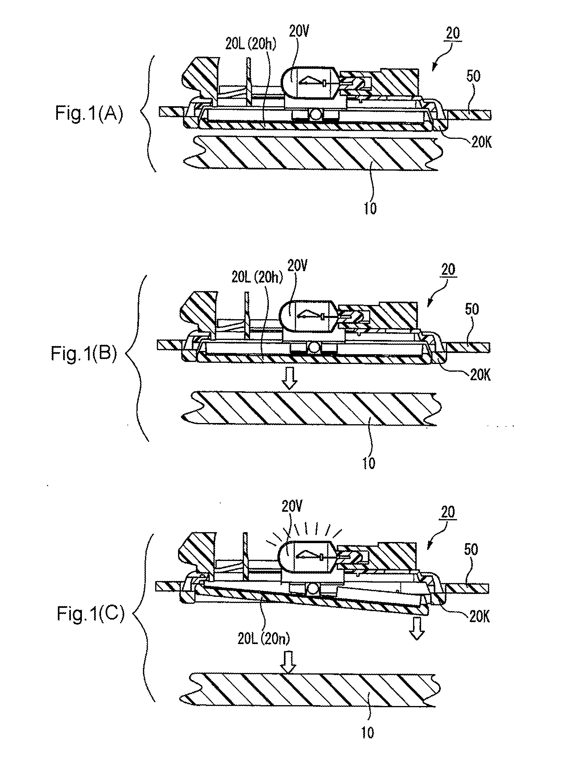
[0049]FIG. 1(A) through FIG. 1(C) illustrate turning on of the lamp in Example 1 of the present invention. They are vertical cross-sectional views illustrating the three steps of operation corresponding to FIG. 1(A), FIG. 1(B), and FIG. 1(C), respectively, until the lamp in the off state is turned on manually. FIG. 1(A) is a vertical cross-sectional view illustrating the case in which the sun visor 10 covers the lamp 20 (lamp is OFF), and FIG. 1(B) is a vertical cross-sectional view illustrating the case in which the sun visor 10 is halfway in the process of retreating from the lamp 20 (lamp is OFF). As the sun visor 10 retreats from the lamp 20, the lens 20L is exposed, so that the driver can manually press the lens 20L. FIG. 1(C) is a vertical cross-sectional view illustrating the case in which the sun visor 10 has retreated from the lamp 20; the lens 20L is manually pressed to become the inclined state and the bulb 20V is turned o...
example 2
Reliable Turning Off of the Lamp 20
[0062]FIG. 3(A) and FIG. 3(B) illustrate Example 2 for more reliably turning off the lamp. FIG. 3(A) is a vertical cross-sectional view corresponding to FIG. 1(C); FIG. 3(B) is a vertical cross-sectional view corresponding to FIG. 2(C).
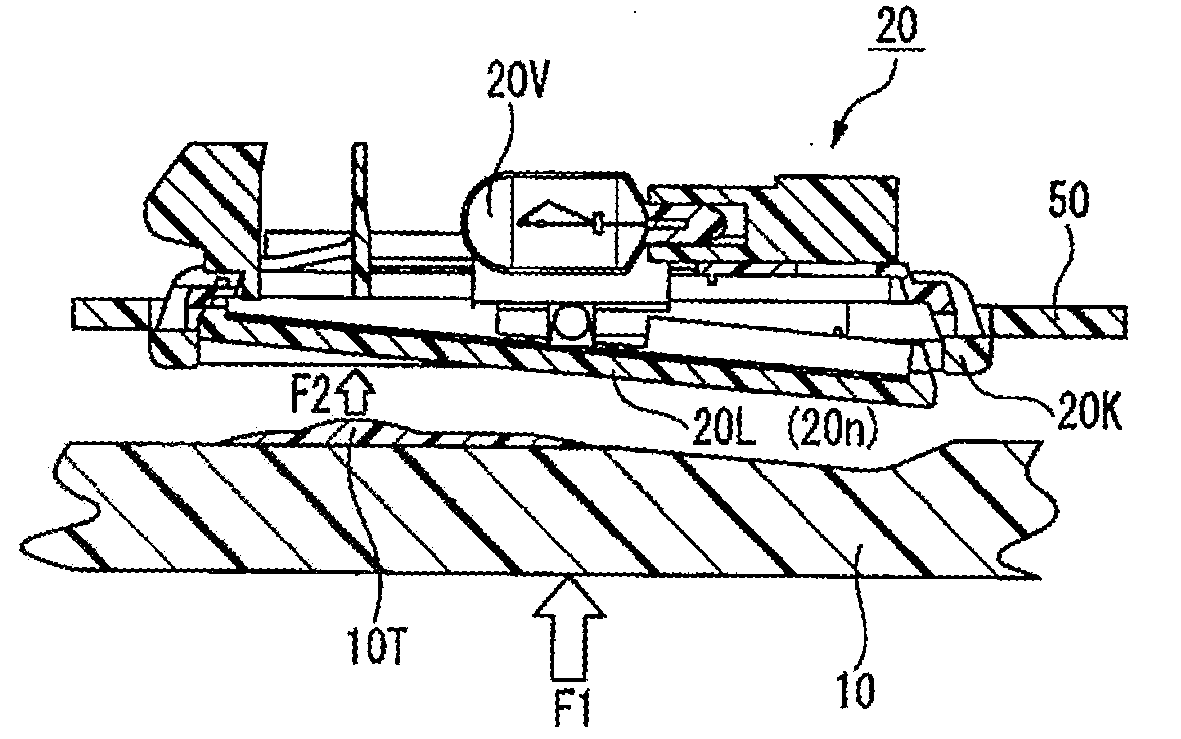
[0063]Here, FIG. 3(A) corresponds to FIG. 1(C) and FIG. 3(B) corresponds to FIG. 2(C). The sun visor 10 shown in FIG. 3 differs from the sun visor 10 shown in FIG. 1(A) to FIG. 1(C) and FIG. 2(A) to FIG. 2(C) in that on the back side of the sun visor 10 (on the side facing the lens 20L of the lamp 20), a protrusion 10T is formed at the position facing the end portion of the lens 20L.
[0064]As shown in FIG. 3(A), the sun visor 10 retreats from the lamp 20, and the lamp 20 is opened. In this state, the driver can use a finger to lightly touch the end portion of the lens 20L (that is, the switch). As a result, as the finger presses the left end portion of the lens 20L, it changes from the horizontal posture to the inclin...
example 3
[0067]Turning Off of the Reversed Type Lamp with Respect to the On / Off Operation
[0068]FIG. 4(A) through FIG. 4(D) illustrate the on / off operation in relation to Example 3 when a lamp of the reversed type is turned off. FIG. 4(A) is an overall oblique view of the lamp in the on state. FIG. 4(B) is a cross-sectional view corresponding to FIG. 3(A). FIG. 4(C) is an overall oblique view of the lamp in the off state. FIG. 4(D) is a cross-sectional view corresponding to FIG. 3(B).
[0069]The sun visor 10 shown in FIG. 4(B) and FIG. 4(D) differs from the sun visor 10 shown in FIG. 3(A) and FIG. 3(B) with respect to the position of the protrusion 10T of the sun visor 10. The protrusion 10T of the sun visor 10 shown in FIG. 3(A) and FIG. 3(B) is at the position where the lens 20L is reset to the horizontal posture. On the other hand, the protrusion 10T of the sun visor 10 shown in FIG. 4(B) and FIG. 4(D) is arranged at the position where the lens 20L in the horizontal posture is changed to the...
PUM
 Abstract
Description
Claims
Application Information