Laser processing machine

Active Publication Date: 2021-05-06
DISCO CORP
View PDF5 Cites 0 Cited by
  • Summary
  • Abstract
  • Description
  • Claims
  • Application Information

AI Technical Summary

Benefits of technology

The invention is a laser processing machine that prevents debris from scattering during processing without reducing efficiency. This results in savings on liquid resin and labor, as well as improved processing performance.

Problems solved by technology

If a liquid resin is applied before performing laser processing on a workpiece as described above, the liquid resin is discarded without reuse after the laser processing, leading to problems that such a technique is uneconomical and has a low productivity due to the need for application and removal steps for the liquid resin.
However, indications have been made about a problem that the laser beam is scattered by bubbles and cavitation occurred in the water, resulting in a failure to perform desired processing.
In addition, a further problem has also been found that individually divided chips have a lowered flexural strength due to effects of heat.

Method used


Image

  • Laser processing machine
  • Laser processing machine
  • Laser processing machine

Examples


Embodiment Construction

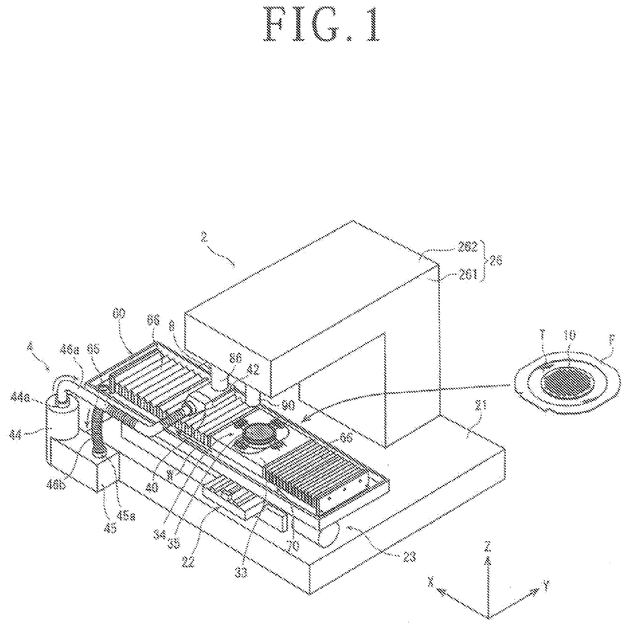
[0021]With reference to the attached drawings, a description will hereinafter be made in detail about a laser processing machine according to an embodiment of the present invention. FIG. 1 is a perspective view of the laser processing machine 2 of this embodiment. The laser processing machine 2 includes a water supply system 4 disposed on a bed 21 and configured to supply water onto a plate-shaped workpiece (for example, a silicon-made wafer 10), a laser beam irradiation unit 8 configured to irradiate a laser beam to the plate-shaped workpiece, a holding unit 22 configured to hold the workpiece, a moving mechanism 23 configured to perform a relative movement of the laser beam irradiation unit 8 and the holding unit 22, and a frame body 26 formed from a vertical wall portion 261, which is disposed upright in a Z direction indicated by an arrow Z on the bed 21 beside the moving mechanism 23, and a horizontal wall portion 262, which extends in a horizontal direction from an upper end p...


PUM


Abstract

A laser processing machine includes a condenser and a water pillar forming unit. The condenser condenses a laser beam emitted from a laser oscillator and irradiates it to a workpiece held on a chuck table. The water pillar forming unit is disposed on a lower end of the condenser and is configured to form a thread-shaped water pillar on a front side of the workpiece. The laser oscillator includes a first laser oscillator, which emits a first laser beam having a short pulse width, and a second laser oscillator, which emits a second laser beam having a long pulse width. After the laser beams emitted from the first and second laser oscillators have transmitted through the thread-shaped water pillar formed by the water pillar forming unit and have been irradiated to the workpiece, a plasma occurred in the water pillar forming unit applies processing to the workpiece.

Description

BACKGROUND OF THE INVENTIONField of the Invention[0001]The present invention relates to a laser processing machine including a chuck table configured to hold a plate-shaped workpiece, a laser beam irradiation unit configured to irradiate a laser beam to the workpiece held on the chuck table so that processing is applied to the workpiece, and a processing feed mechanism configured to perform relative processing feed of the chuck table and the laser beam irradiation unit.Description of the Related Art[0002]A wafer, on a front side of which a plurality of devices such as integrated circuits (ICs), large scale integrated circuits (LSIs) or the like are formed and defined by a plurality of intersecting streets, is divided into the individual devices by a laser processing machine, and the thus-divided device chips are used in electrical equipment such as mobile phones, personal computers, lighting equipment or the like.[0003]On the other hand, there are a variety of types of laser process...

Claims


Application Information

Patent Timeline
IPC IPC(8): B23K26/146B23K26/0622B23K26/06B23K26/064B23K26/08B23K26/142H01L21/67
CPCB23K26/146B23K26/0622B23K26/0608B23K26/0648B23K26/0665B23K2101/18B23K26/08B23K26/142H01L21/67092H01L21/67115B23K26/064B23K2103/56H01L21/6704H01L21/6715H01L21/68B23K26/402B23K26/703B23K2101/40
Inventor NOMARU, KEIJIHADANO, YUJI
Owner DISCO CORP
Why Eureka
Try Eureka