Windshield wiper combining assembly of combining driven wiper arm

a technology of driving wiper arm and windshield wiper, which is applied in the direction of vehicle maintenance, vehicle cleaning, domestic applications, etc., can solve the problem of easy production of loose attachment of two components

Inactive Publication Date: 2013-01-10
DANYANG UPC AUTO PARTS
View PDF2 Cites 2 Cited by
  • Summary
  • Abstract
  • Description
  • Claims
  • Application Information

AI Technical Summary

Benefits of technology

[0012]The block is plunged into the engaging groove and the cover cap is pressed on the containing groove to prevent loose attachment of the through shaft from the containing groove when the retaining stage is pushed to make the cover cap abut the containing groove.
[0013]Another object of the invention is to provide a windshield wiper combining assembly of combining a driven wiper arm so that two side edges of the driven wiper arm are fastened at two sides of the assembling stage to prevent the driven wiper arm from sway and position deviation.
[0014]Comparing with the prior art, the through shaft of the driven wiper arm of the present invention is arranged in the assembling stage and the retaining stage is positioned on the assembling stage. The block is plunged into the engaging groove and the cover cap is pressed on the containing groove to prevent loose attachment of the through shaft from the containing groove when the retaining stage is pushed to make the cover cap abut the containing groove. Therefore, the driven wiper arm can be firmly assembled on the assembling stage.

Problems solved by technology

The combination configuration of the driven wiper arm and the assembling stage is used for a period of time, however, it is easily to produce loose attachment of the two components.

Method used


Image

  • Windshield wiper combining assembly of combining driven wiper arm
  • Windshield wiper combining assembly of combining driven wiper arm
  • Windshield wiper combining assembly of combining driven wiper arm

Examples


Embodiment Construction

[0025]Reference will now be made to the drawing figures to describe the present invention in detail. Although the present invention has been described with reference to the preferred embodiment thereof, it will be understood that the invention is not limited to the details thereof.

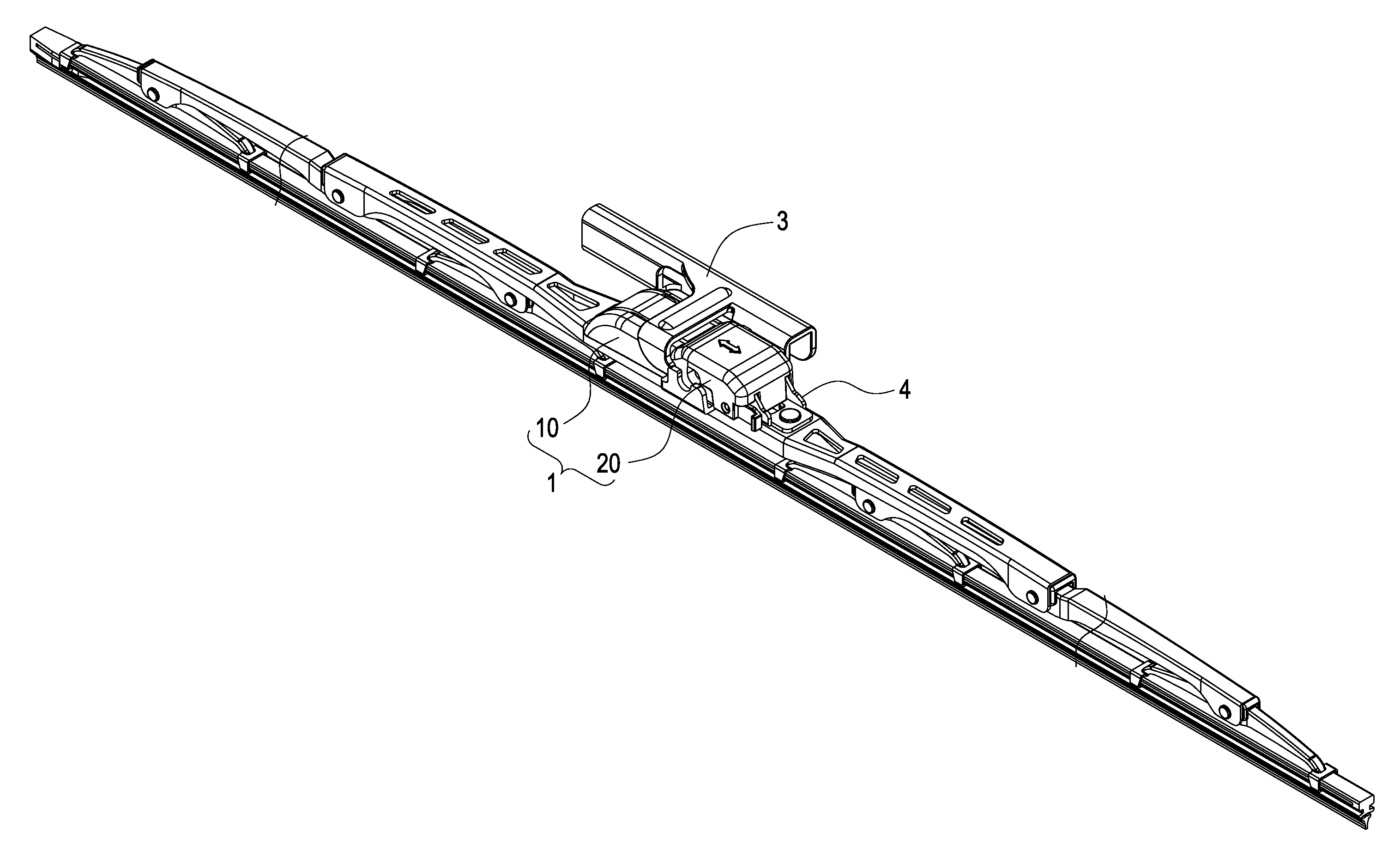
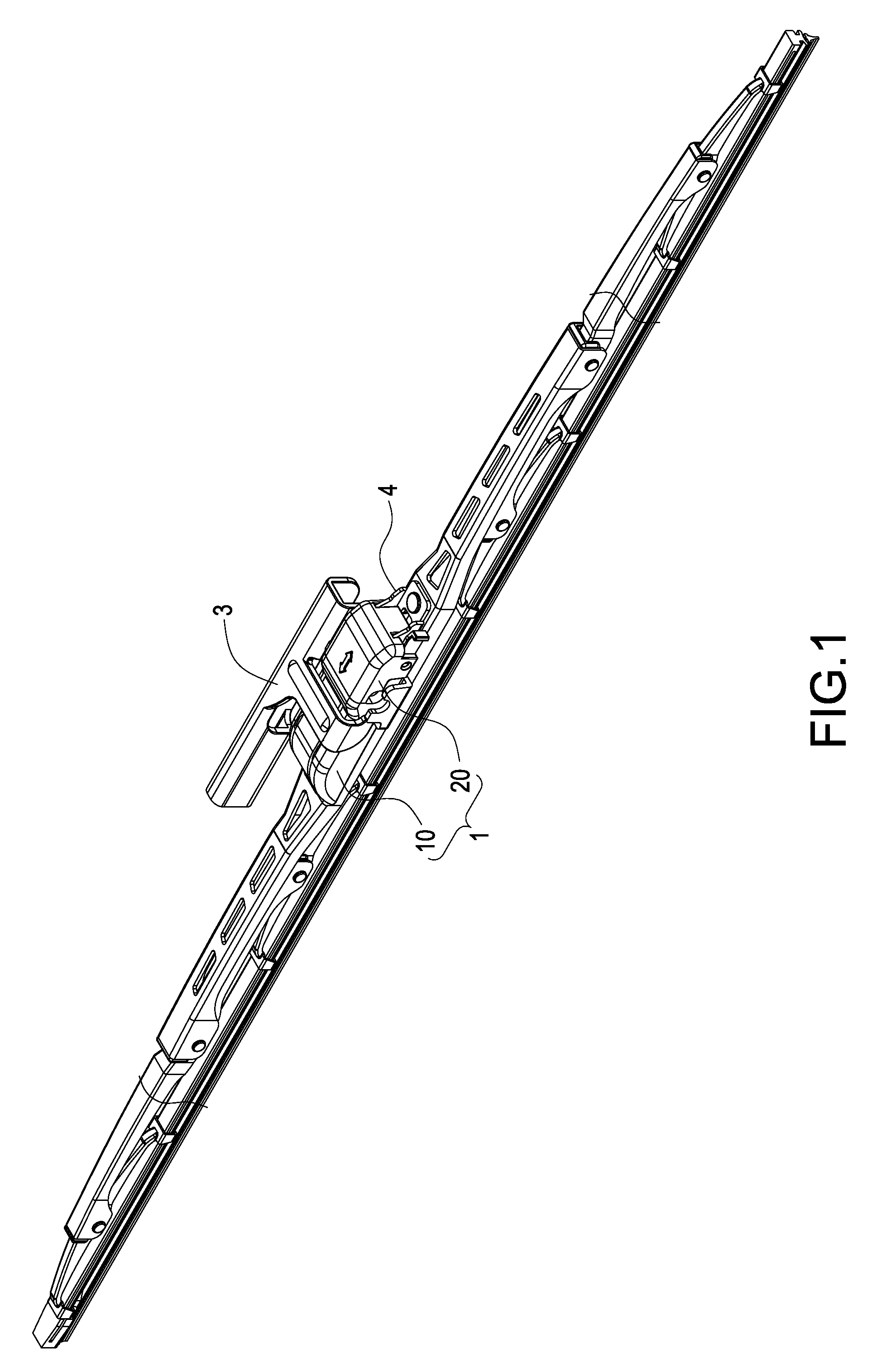
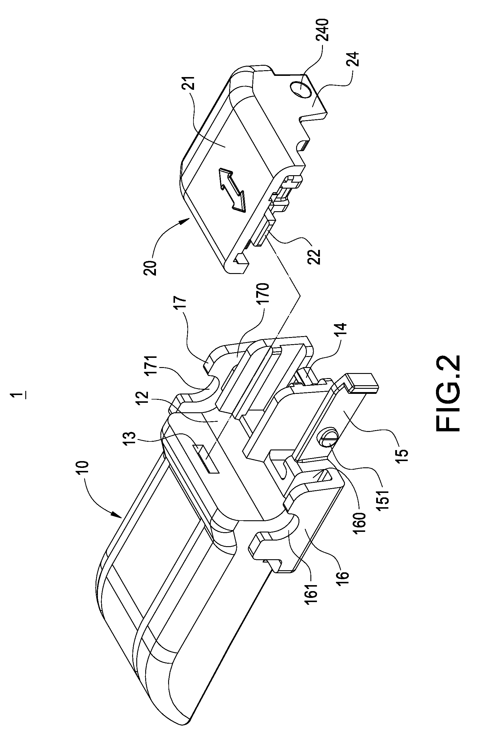
[0026]Reference is made from FIG. 1 to FIG. 5 which are a schematic view of using a windshield wiper combining assembly, a first and a second schematic perspective assembled views of the windshield wiper combining assembly, a schematic assembled view of the windshield wiper combining assembly and a windshield wiper fixing stage, and a schematic view of combining the windshield wiper combining assembly to a driven wiper arm according to the present invention, respectively. The present invention discloses a windshield wiper combining assembly of combining the driven wiper arm. The windshield wiper combining assembly 1 assemblies a driven wiper arm 3 with a through shaft 2 on the windshield wiper fixing stage...


PUM


Abstract

A windshield wiper combining assembly assembles a driven wiper arm having a through shaft on a windshield wiper fixing stage. The windshield wiper combining assembly includes an assembling stage and a retaining stage. The assembling stage engages on the windshield wiper fixing stage. The assembling stage has a first fastening arm, a containing groove formed at one side edge of the assembling stage to contain the through shaft, and an engaging groove arranged at one side edge of the containing groove. The retaining stage has a cover cap and a block which projects on an end surface of the cover cap. The retaining stage is combined on the assembling stage by fastening the first fastening arm. The block is plunged into the engaging groove and the cover cap is pressed on the containing groove to prevent loose attachment of the through shaft.

Description

BACKGROUND OF THE INVENTION[0001]1. Field of the Invention[0002]The present invention relates generally to a windshield wiper configuration, and more particularly to a windshield wiper combining assembly of combining a driven wiper arm.[0003]2. Description of Prior Art[0004]In general, a windshield wiper for a vehicle is installed on a vehicle window of the vehicle. The windshield wiper is connected to a driven wiper arm of the vehicle and the windshield wiper is repeatedly wiped on the vehicle window by applying force on the windshield wiper via the driven wiper arm.[0005]The available windshield wiper on the market mainly includes an assembling stage, a fixing stage, and a supporting rack. The supporting rack installs rubber-made wiper blades on a bottom surface of the supporting rack. The supporting rack is assembled on a bottom surface of the fixing stage and the assembling stage is installed on a top surface of the fixing stage so that the driven wiper arm of the vehicle can be...

Claims


Application Information

Patent Timeline
Patent Type & Authority Applications(United States)
IPC IPC(8): B60S1/40
CPCB60S1/407B60S1/4077B60S1/4074
Inventor YANG, CHIH-MINGCHANG, CHUAN-CHIH
Owner DANYANG UPC AUTO PARTS
Why Eureka
Try Eureka