Electronic device

a technology of electronic devices and touch screens, applied in the direction of electric digital data processing, instruments, computing, etc., can solve the problems of insufficient tactile presentation, inability of operators to determine whether an input operation has been properly performed, and fact has imposed substantial stress on operators of conventional touch screen panels, so as to achieve the effect of alleviating inconsistencies in tactile sensation depending on the touched position

Active Publication Date: 2013-01-10
PANASONIC INTELLECTUAL PROPERTY MANAGEMENT CO LTD
View PDF3 Cites 21 Cited by
  • Summary
  • Abstract
  • Description
  • Claims
  • Application Information

AI Technical Summary

Benefits of technology

[0011]In accordance with the non-limiting and exemplary electronic device disclosed herein, inconsistencies in tactile sensation depending on the touched position can be alleviated.

Problems solved by technology

Thus, the operator is unable to determine whether an input operation has been properly made by relying on a tactile sensation at his or her fingertip.
This fact has imposed substantial stress on the operators of conventional touch screen panels.
Upon studying the tactile presentation function of the touch screen panel disclosed in Patent Document 1, the inventors have found that the tactile presentation may not be sufficient, e.g., the operator may feel oddness, or the vibration may not be provided at a sufficient intensity.

Method used


Image

  • Electronic device
  • Electronic device
  • Electronic device

Examples


embodiment 1

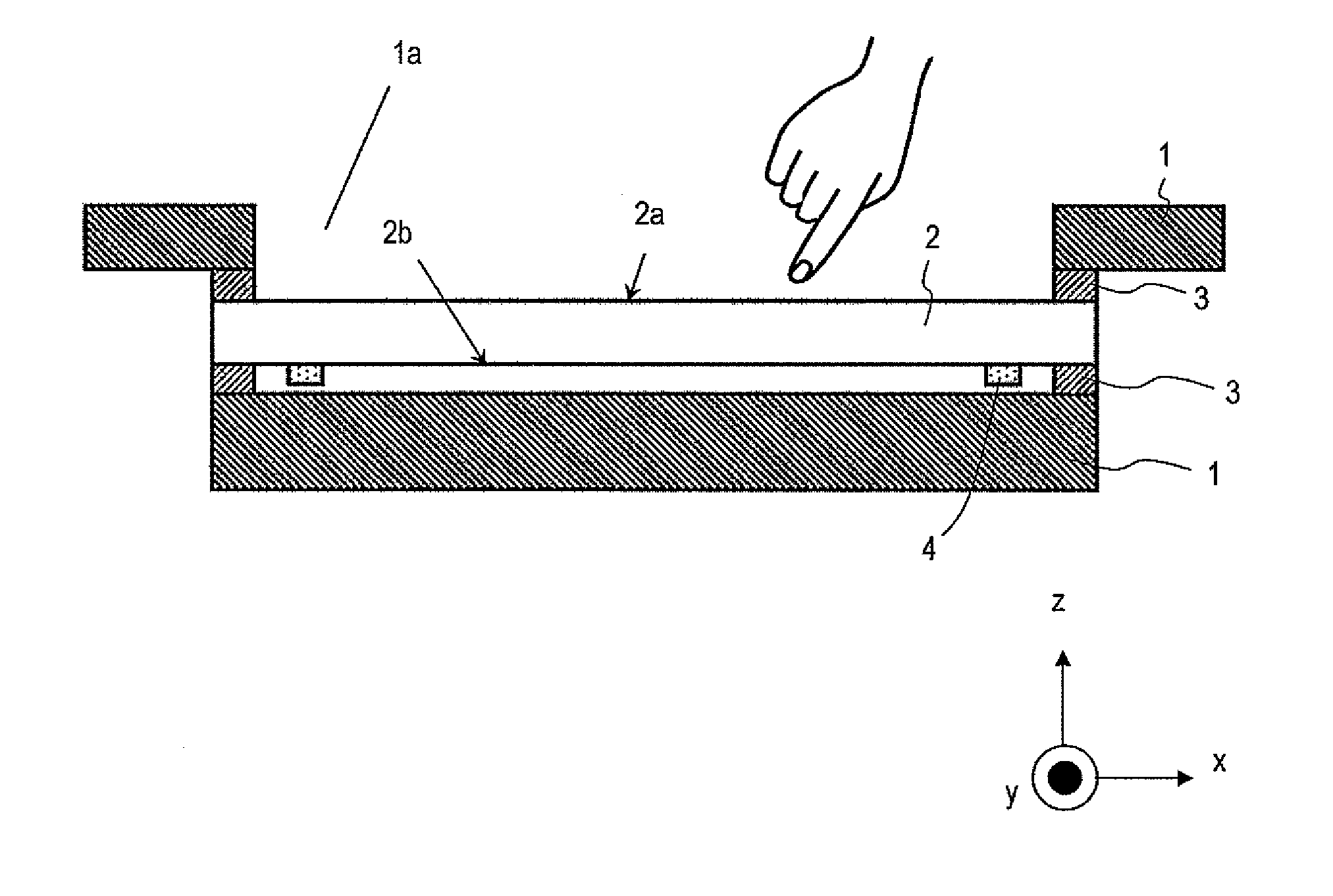
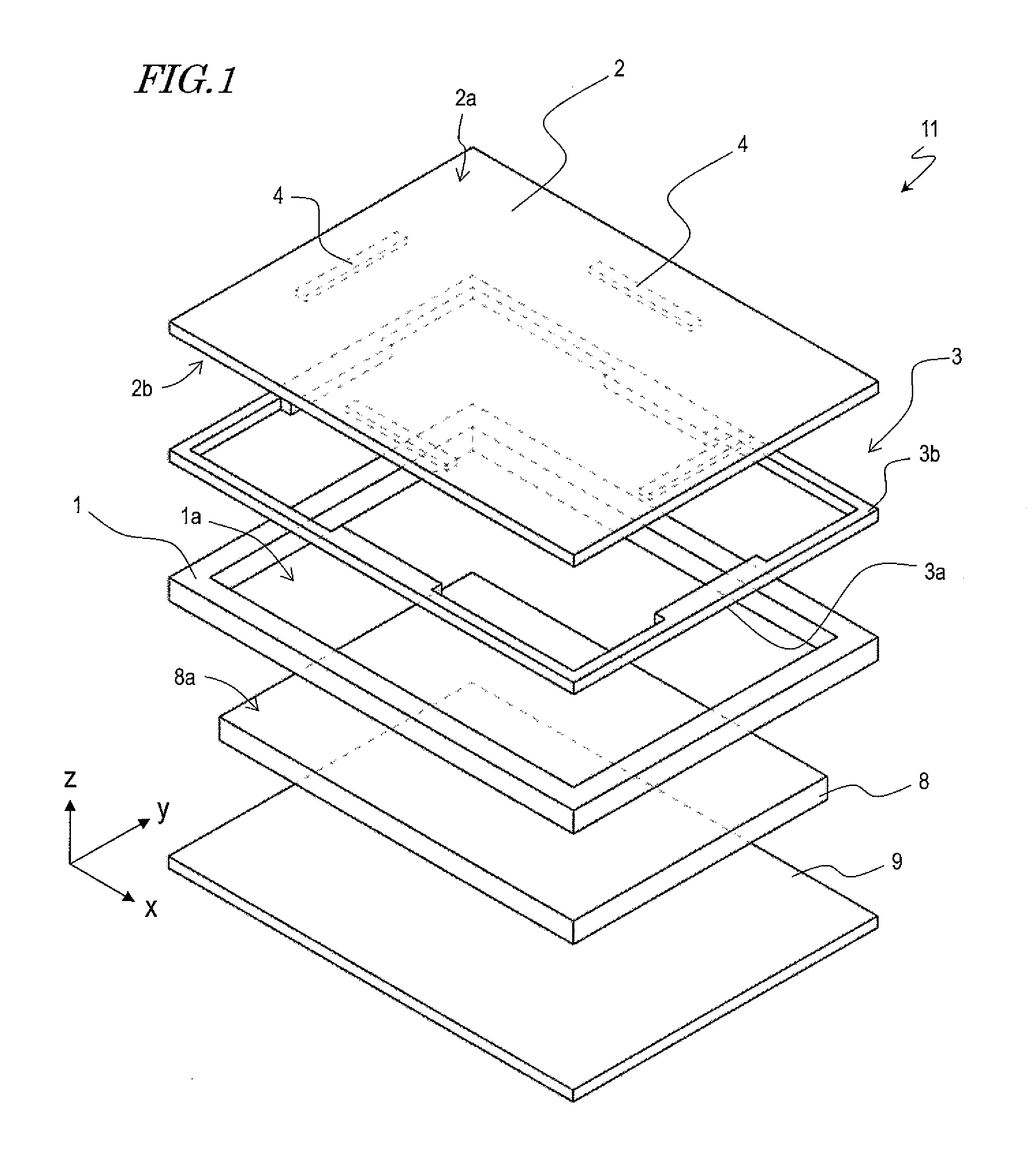
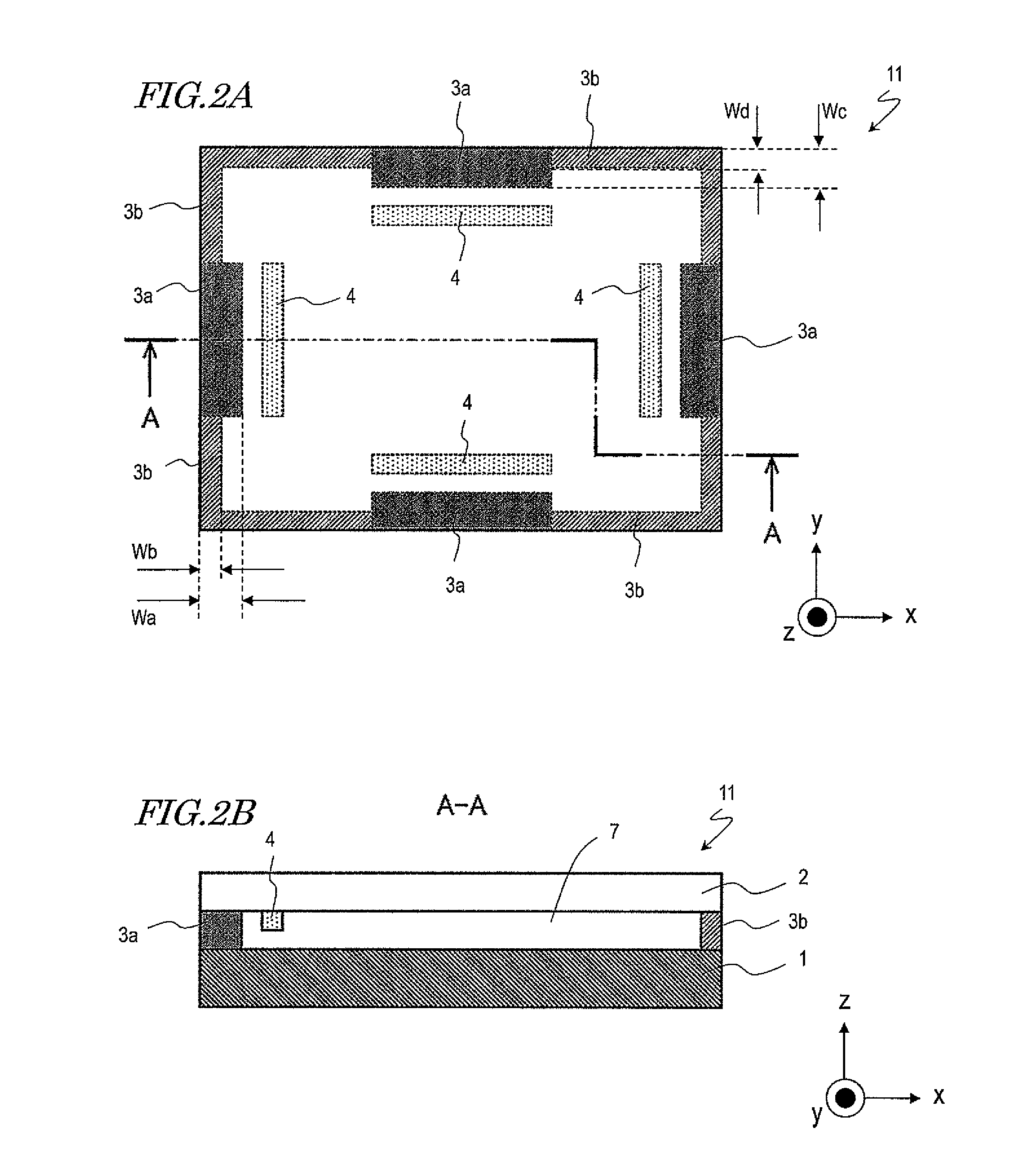
[0032]Hereinafter, with reference to the figures, an electronic device 11 according to the present embodiment will be described. FIG. 1 is an exploded perspective view schematically showing the construction of the electronic device 11. FIG. 2A is an upper plan view of the electronic device 11. FIG. 2B is a cross-sectional view of the electronic device 11 taken along A-A.

[0033]Now, an x direction, a y direction, and a z direction are defined for the sake of explanation. As shown in FIG. 1, the longitudinal direction of the electronic device 11 is defined as the x direction. The lateral direction of the electronic device 11 is defined as the y direction. The thickness direction of the electronic device 11 is defined as the z direction.

Construction

[0034]As shown in FIG. 1, the electronic device 11 includes a base 1, a touch screen panel 2, a support structure 3, and vibration mechanisms 4. The electronic device 11 also includes a display device 8 and a control substrate 9, for example....

embodiment 2

[0049]Hereinafter, with reference to the figures, an electronic device 12 according to the present embodiment will be described. In Embodiment 1, the width of the first support members 3a is made larger than the width of the second support members 3b, thus increasing the rigidity of the first support members 3a over the rigidity of the second support members 3b. In the present embodiment, the first and second support members 3a and 3b have an equal width. In the present embodiment, a cross-sectional shape of the first support members 3a and a cross-sectional shape of the second support members 3b are different, unlike in Embodiment 1. Therefore, any members having their counterparts in Embodiment 1 will be denoted by like numerals, and mainly the support structure 3 of the present embodiment will be described.

Construction

[0050]FIG. 3A is an upper plan view of the electronic device 12. FIG. 3B is a cross-sectional view of the electronic device 12 taken along A-A. FIG. 4 is a cross-se...

embodiment 3

[0055]Hereinafter, with reference to the figures, an electronic device 13 according to Embodiment 3 will be described. In the present embodiment, the thickness of the first support members 3a along the z direction is different from the thickness of the second support members 3b along the z direction, unlike in Embodiment 1. Therefore, any members having their counterparts in Embodiment 1 will be denoted by like numerals, and mainly the support structure 3 of the present embodiment will be described.

Construction

[0056]FIG. 6A is an upper plan view of the electronic device 13. FIG. 6B is a side view of the electronic device 13.

[0057]As shown in FIG. 6A, the first support members 3a are positioned closer to the vibration mechanisms 4 than are second support members 3b. Moreover, as shown in FIG. 6B, the base 1 of the present embodiment has bumps 1t in regions corresponding to the first support members 3a. As a result, the thickness of the first support members 3a along the z direction, ...


PUM


Abstract

An electronic device includes: a touch screen panel; a support structure having a first support member and a second support member, the first support member and the second support member being in contact with touch screen panel to support the touch screen panel at a periphery of the touch screen panel; a base being in contact with the support structure to support the touch screen panel via the support structure; and a vibration mechanism for vibrating the touch screen panel, the vibration mechanism being provided near the periphery of the touch screen panel so as to be closer to the first support member than to the second support member. The first support member has a rigidity which is greater than a rigidity of the second support member.

Description

BACKGROUND[0001]1. Technical Field[0002]The present disclosure relates to an electronic device having a touch screen panel.[0003]2. Description of the Related Art[0004]Electronic devices having a touch screen panel as an input device on the surface of a display have conventionally been in wide use. One operation principle for such a touch screen panel is an electrostatic method. Under this method, a change in the electrostatic capacity between a fingertip of an operator and an electrically conductive film of the touch screen panel is detected, whereby the position on the panel that is being touched by the operator's fingertip is detected.[0005]Generally speaking, an electronic device having a touch screen panel accepts an input as an operator directly touches on the panel surface. At this time, even if the operator's touch on the panel surface causes a change in electrostatic capacity, the operator has no tactile knowledge of it. Thus, the operator is unable to determine whether an ...

Claims


Application Information

Patent Timeline
Patent Type & Authority Applications(United States)
IPC IPC(8): G06F3/041
CPCG06F3/041G06F2203/04103G06F3/016
Inventor OKUMURA, RYOADACHI, YUSUKE
Owner PANASONIC INTELLECTUAL PROPERTY MANAGEMENT CO LTD
Why Eureka
Try Eureka