Electronic device having touch screen panel, vibration mechanisms, and peripheral support structures having different rigidities
a touch screen panel and electronic device technology, applied in the field of electronic devices having touch screen panels, can solve the problems of insufficient tactile presentation, inability to determine whether an input operation has been properly performed, and fact has imposed substantial stress on the operators of conventional touch screen panels, so as to achieve the effect of alleviating the inconsistency of tactile sensation depending on the touched position
- Summary
- Abstract
- Description
- Claims
- Application Information
AI Technical Summary
Benefits of technology
Problems solved by technology
Method used
Image
Examples
embodiment 1
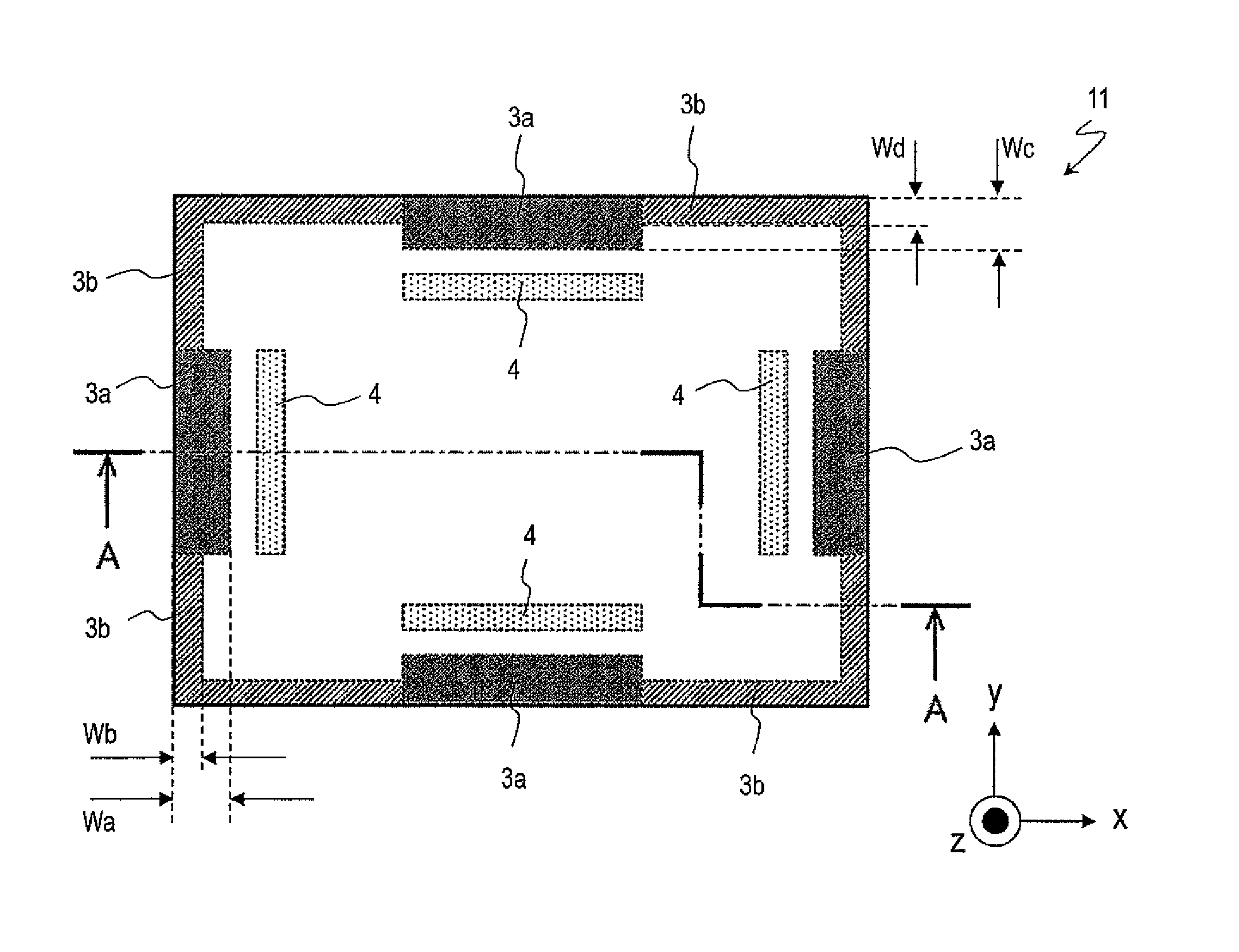
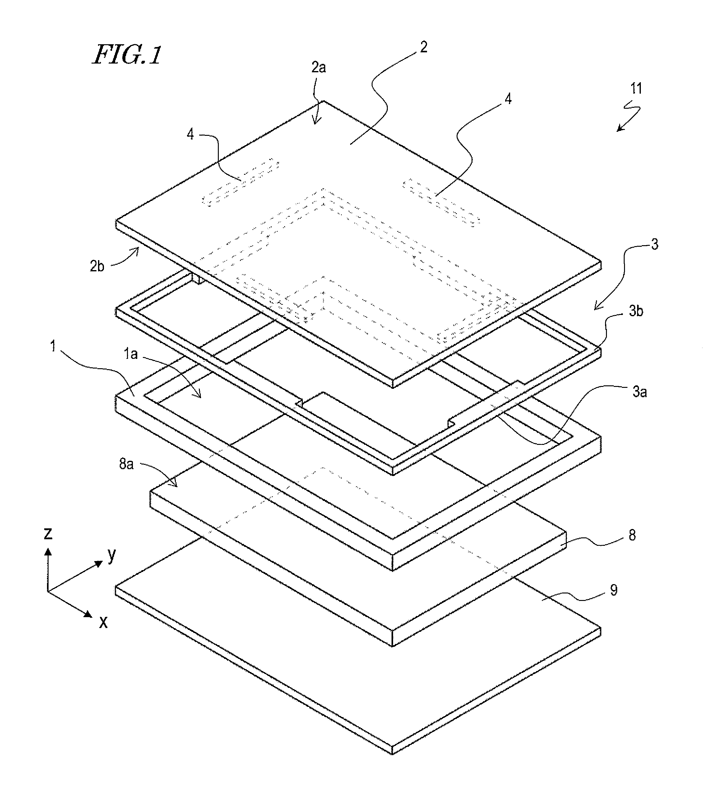
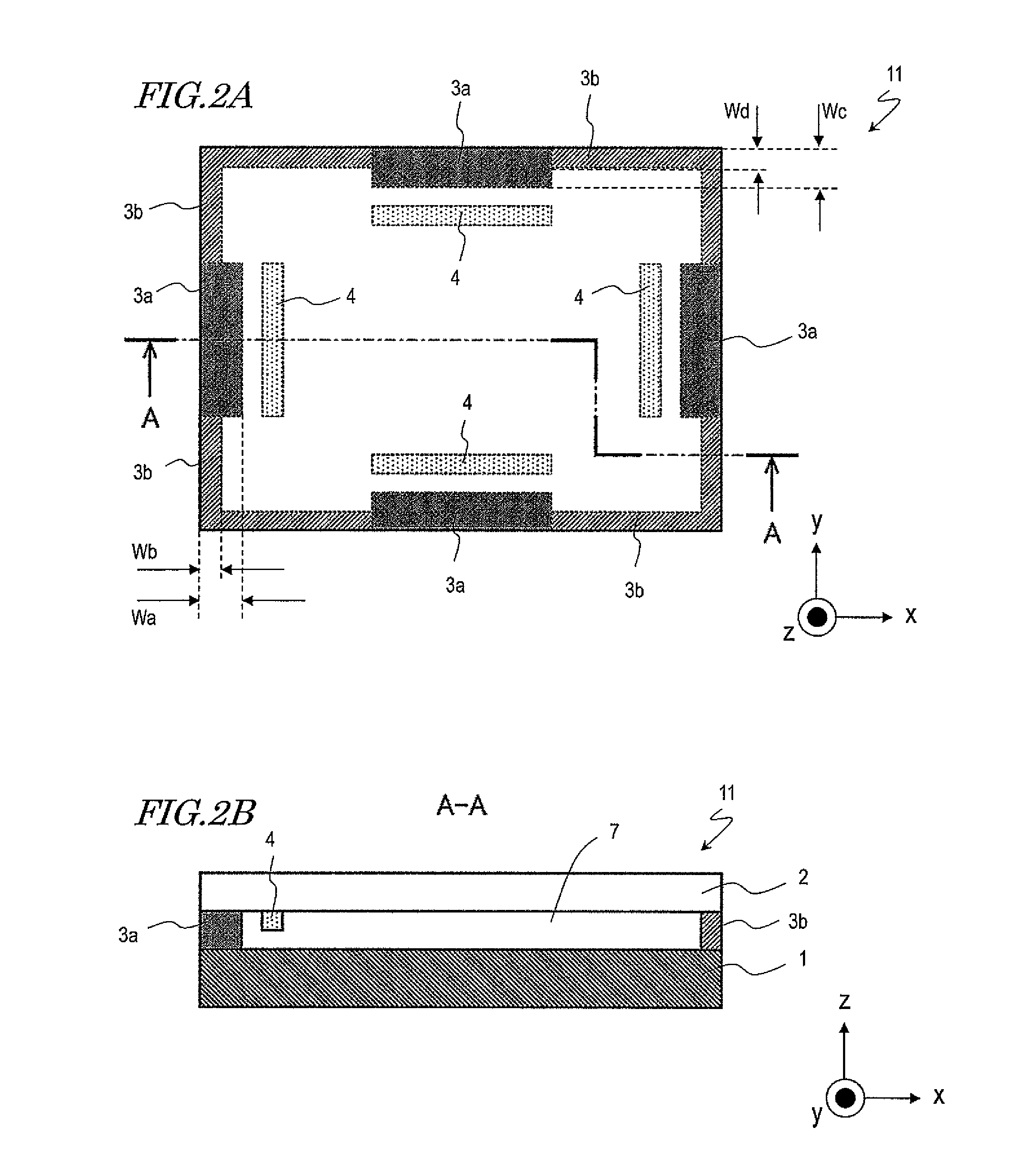
[0032]Hereinafter, with reference to the figures, an electronic device 11 according to the present embodiment will be described. FIG. 1 is an exploded perspective view schematically showing the construction of the electronic device 11. FIG. 2A is an upper plan view of the electronic device 11. FIG. 2B is a cross-sectional view of the electronic device 11 taken along A-A.
[0033]Now, an x direction, a y direction, and a z direction are defined for the sake of explanation. As shown in FIG. 1, the longitudinal direction of the electronic device 11 is defined as the x direction. The lateral direction of the electronic device 11 is defined as the y direction. The thickness direction of the electronic device 11 is defined as the z direction.
Construction
[0034]As shown in FIG. 1, the electronic device 11 includes a base 1, a touch screen panel 2, a support structure 3, and vibration mechanisms 4. The electronic device 11 also includes a display device 8 and a control substrate 9, for example....
embodiment 2
[0049]Hereinafter, with reference to the figures, an electronic device 12 according to the present embodiment will be described. In Embodiment 1, the width of the first support members 3a is made larger than the width of the second support members 3b, thus increasing the rigidity of the first support members 3a over the rigidity of the second support members 3b. In the present embodiment, the first and second support members 3a and 3b have an equal width. In the present embodiment, a cross-sectional shape of the first support members 3a and a cross-sectional shape of the second support members 3b are different, unlike in Embodiment 1. Therefore, any members having their counterparts in Embodiment 1 will be denoted by like numerals, and mainly the support structure 3 of the present embodiment will be described.
Construction
[0050]FIG. 3A is an upper plan view of the electronic device 12. FIG. 3B is a cross-sectional view of the electronic device 12 taken along A-A. FIG. 4 is a cross-se...
embodiment 3
[0055]Hereinafter, with reference to the figures, an electronic device 13 according to Embodiment 3 will be described. In the present embodiment, the thickness of the first support members 3a along the z direction is different from the thickness of the second support members 3b along the z direction, unlike in Embodiment 1. Therefore, any members having their counterparts in Embodiment 1 will be denoted by like numerals, and mainly the support structure 3 of the present embodiment will be described.
Construction
[0056]FIG. 6A is an upper plan view of the electronic device 13. FIG. 6B is a side view of the electronic device 13.
[0057]As shown in FIG. 6A, the first support members 3a are positioned closer to the vibration mechanisms 4 than are second support members 3b. Moreover, as shown in FIG. 6B, the base 1 of the present embodiment has bumps 1t in regions corresponding to the first support members 3a. As a result, the thickness of the first support members 3a along the z direction, ...
PUM
 Abstract
Description
Claims
Application Information
 - R&D
- Intellectual Property
- Life Sciences
- Materials
- Tech Scout
- Unparalleled Data Quality
- Higher Quality Content
- 60% Fewer Hallucinations
Browse by: Latest US Patents, China's latest patents, Technical Efficacy Thesaurus, Application Domain, Technology Topic, Popular Technical Reports.
© 2025 PatSnap. All rights reserved.Legal|Privacy policy|Modern Slavery Act Transparency Statement|Sitemap|About US| Contact US: help@patsnap.com


