Vibration actuator and method for driving vibration actuator

a technology of vibration actuator and actuator, which is applied in the direction of mechanical vibration separation, mechanical pattern conversion, instruments, etc., can solve the problem of reducing the user's tactile sensation

Active Publication Date: 2022-07-05
COPAL CO LTD
View PDF4 Cites 0 Cited by
  • Summary
  • Abstract
  • Description
  • Claims
  • Application Information

AI Technical Summary

Benefits of technology

[0006]A larger touch panel may incorporate multiple tactile devices to provide sufficient vibrations. However, the tactile devices may be linear resonant actuators that have, for example, variations of about several percent in resonant frequency caused by manufacturing variations, environmental factors (e.g., temperature), and changes over time. Different tactile devices may thus have different optimum driving frequencies. Such tactile devices vibrating individually at their optimum frequencies may produce largely disturbed vibrations on the touch panel, possibly reducing the user's tactile sensation.
[0007]In response to the above issue, one or more aspects of the present invention are directed to a vibration actuator and a method for driving the vibration actuator that can improve the user's tactile sensation.
[0017]The vibration actuator and the method for driving the vibration actuator according to the above aspects of the present invention can improve the user's tactile sensation.

Problems solved by technology

However, touch panels provide a less tactile sensation, unlike operation with known mechanical buttons.
Such tactile devices vibrating individually at their optimum frequencies may produce largely disturbed vibrations on the touch panel, possibly reducing the user's tactile sensation.

Method used


Image

  • Vibration actuator and method for driving vibration actuator
  • Vibration actuator and method for driving vibration actuator
  • Vibration actuator and method for driving vibration actuator

Examples


Embodiment Construction

[0030]Embodiments of the present invention will now be described in detail with reference to the drawings. Throughout the drawings describing the embodiments, the same components are basically given the same reference numerals and will not be described repeatedly.

Overview of Touch Panel System

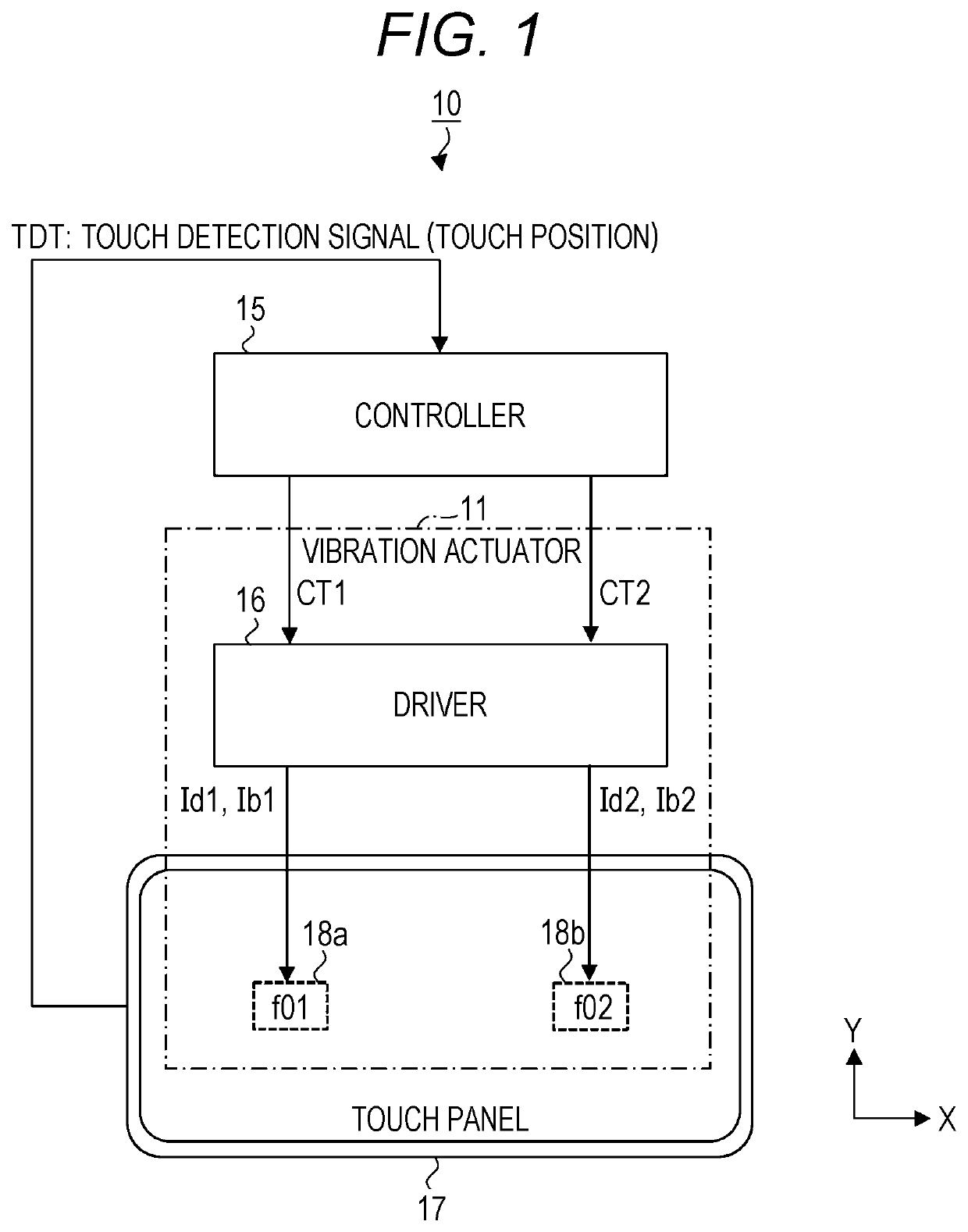
[0031]FIG. 1 is a schematic diagram of an example touch panel system including a vibration actuator according to an embodiment of the present invention. A touch panel system 10 shown in FIG. 1 includes a vibration actuator 11, a controller 15, and a touch panel 17. The vibration actuator 11 is used for the touch panel 17. The vibration actuator 11 includes multiple (two in this example) tactile devices 18a and 18b and a driver 16. The multiple tactile devices herein are collectively referred to as tactile devices 18.

[0032]The tactile devices 18a and 18b are attached at different positions on the surface of the touch panel 17. One direction along the surface of the touch panel 17 is herein defin...


PUM


Abstract

A vibration actuator and a method for driving the vibration actuator can improve the user's tactile sensation. A plurality of tactile devices are attachable at different positions on a surface of a touch panel to vibrate the touch panel. A driver drives, in response to a touch detection signal representing a touch position from the touch panel, the plurality of tactile devices each using a driving signal having a predetermined driving frequency. Of the plurality of tactile devices, a tactile device closest to the touch position is operable as a master device, and a tactile device other than the master device is operable as a slave device. The master device and the slave device are driven using the driving signal having the driving frequency being a resonant frequency of the master device.

Description

RELATED APPLICATIONS[0001]The present application claims priority to Japanese Application Number 2020-057245, filed Mar. 27, 2020, the disclosure of which is hereby incorporated by reference herein in its entirety.BACKGROUNDTechnical Field[0002]The present invention relates to a vibration actuator and a method for driving the vibration actuator.Description of the Background[0003]Patent Literature 1 describes a vibration actuator including multiple vibrators with different resonant frequencies. A method described in Patent Literature 1 allows the vibration actuator to vibrate at different frequencies and large amplitudes, and allows an operator to receive feedback of different vibrations in response to, for example, different operational inputs.CITATION LISTPatent Literature[0004]Patent Literature 1: Japanese Unexamined Patent Application Publication No. 2019-785BRIEF SUMMARY[0005]Touch panels are common in various fields, including home appliances, mobile devices (e.g., smartphones ...

Claims


Application Information

Patent Timeline
Patent Type & Authority Patents(United States)
IPC IPC(8): G06F3/01G06F3/041B06B1/02B06B1/04
CPCG06F3/016B06B1/0223B06B1/04G06F3/0412G06F3/0416B06B1/0253B06B2201/70B06B1/045
Inventor HORI, HIROYUKI
Owner COPAL CO LTD
Why Eureka
Try Eureka