Optical connector

a technology of optical connectors and connectors, applied in the field of optical connectors, can solve problems such as increasing operation costs

Inactive Publication Date: 2013-01-10
JAPAN AVIATION ELECTRONICS IND LTD
View PDF38 Cites 1 Cited by
  • Summary
  • Abstract
  • Description
  • Claims
  • Application Information

AI Technical Summary

Benefits of technology

[0009]The present invention has been made in view of these circumstances, and an object thereof is to provide an optical connector which makes it possible to remove a ferrule from a housing without using a special jig.
[0011]With the arrangement of the optical connector according to the present invention, the supporting member includes the supporting member main body received in the housing, and the operating portion provided on the supporting member main body, which temporarily disables the retaining function of the retaining means, and when the supporting member is mounted in the housing, the operating portion protrudes out from the housing, and hence it is possible to temporarily disable the retaining function of the retaining means by manually operating the operating portion, whereby it is possible to easily draw out the supporting member from the housing. As a result, the ferrule is removed from the housing in a state supported by the supported member.
[0015]Further preferably, the connection portion is formed with an accommodating portion for accommodating a flange portion of the ferrule, and preventing the flange portion from moving in a direction of inserting or removing the supporting member.
[0016]According to this invention, it is possible to easily remove the ferrule from the housing by an operator alone.

Problems solved by technology

This is a cause of an increase in operation costs.

Method used


Image

  • Optical connector
  • Optical connector
  • Optical connector

Examples


first embodiment

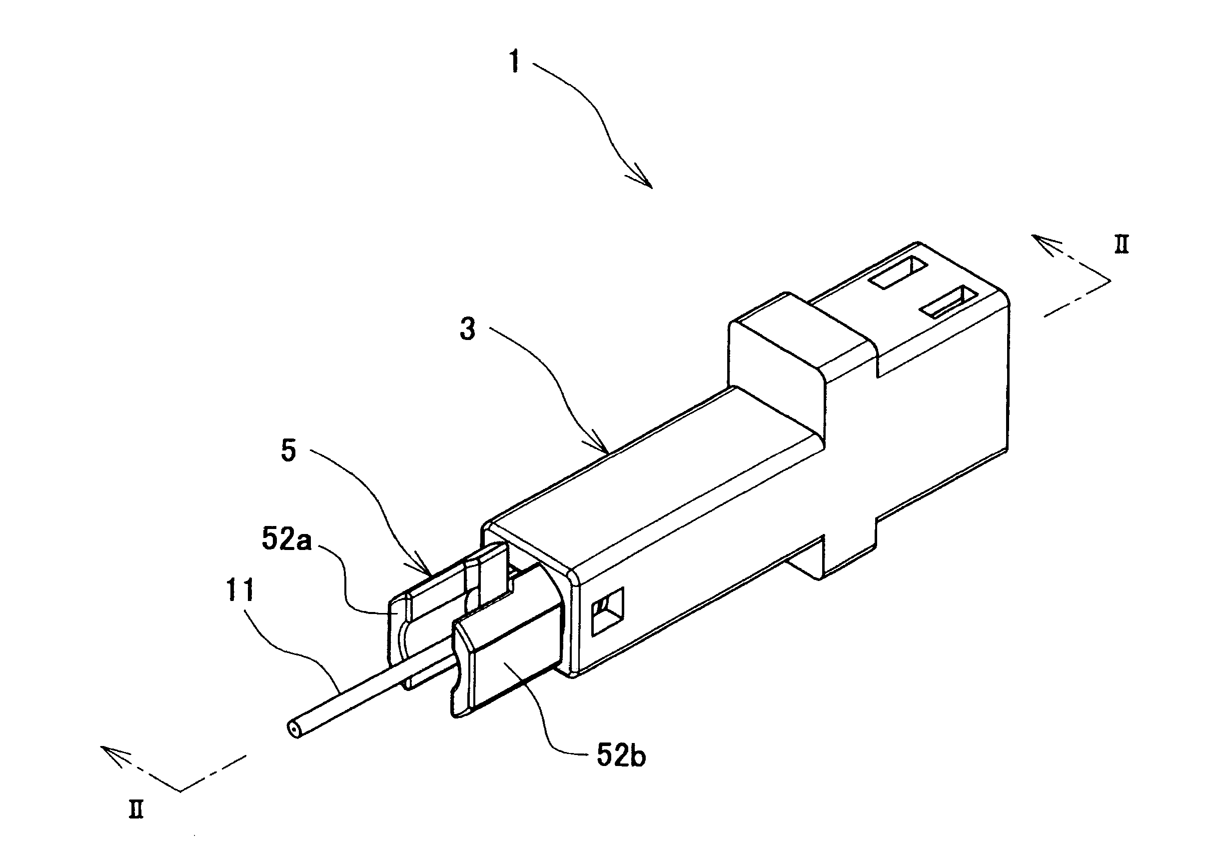
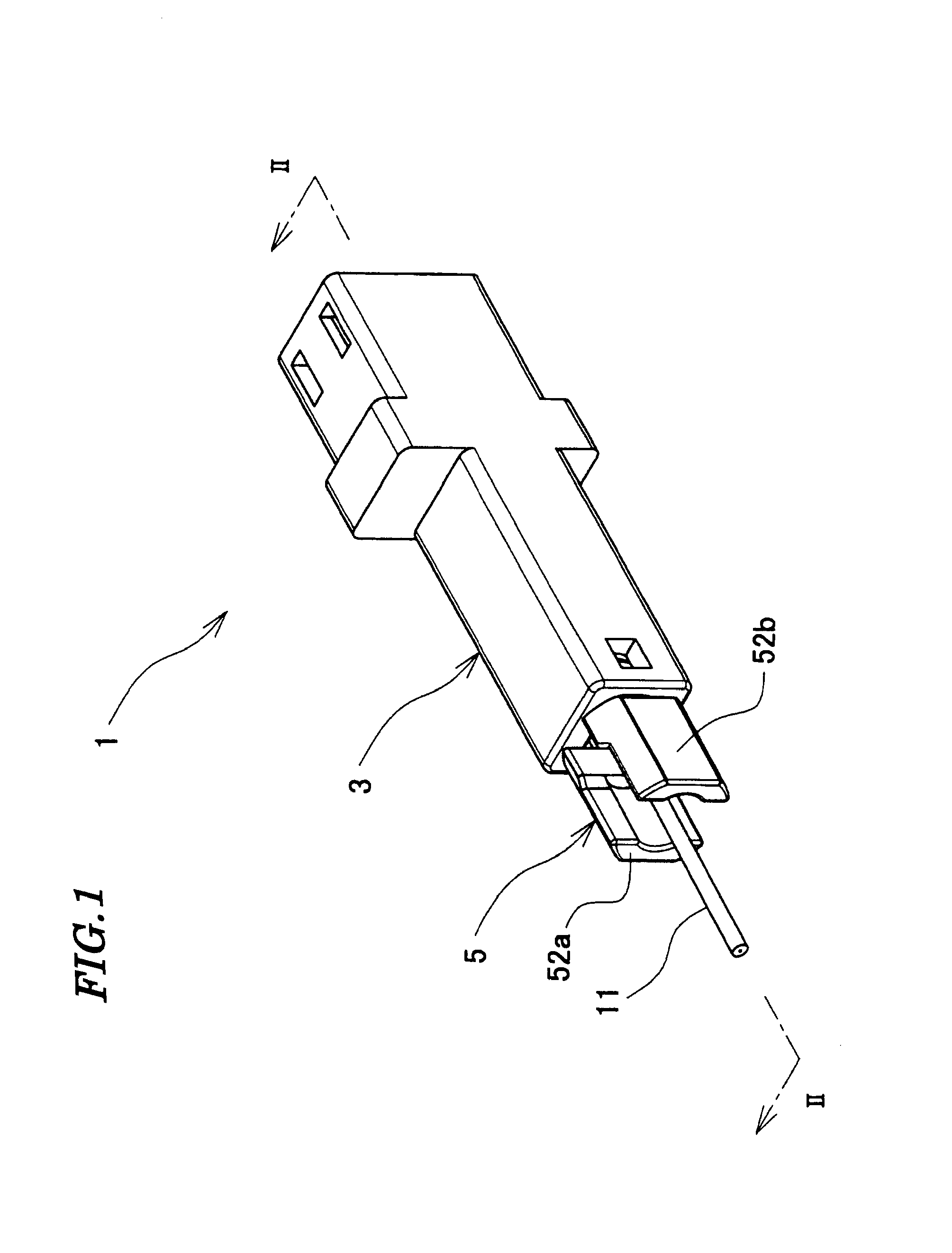
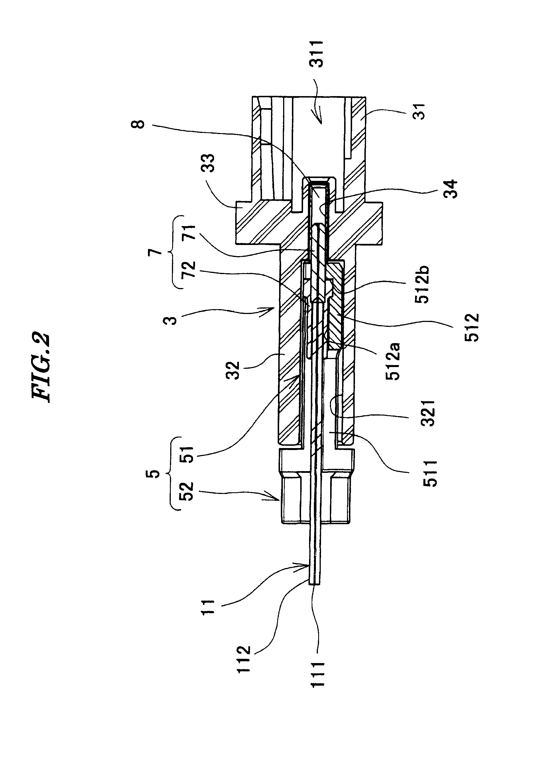
[0037]A description will be given of an optical connector 1 according to the present invention with reference to FIGS. 1 to 15.

[0038]As shown in FIGS. 1 and 2, the optical connector 1 is comprised of a housing 3, a supporting member 5, a ferrule 7, and a divided sleeve 8.

[0039]As shown in FIGS. 2, 3, and 4, the housing 3 includes a fitting portion 31 and a supporting member-receiving portion 32. The fitting portion 31 is in the form of a box having an opening, and has a receiving space 311 (see FIG. 2). The receiving space 311 receives a front end portion of a mating housing of a mating optical connector, not shown. The fitting portion 31 has an upper surface formed with locking holes 312. When the mating housing is inserted into the receiving space 311, locking lugs (not shown) formed on the mating housing are engaged with the locking holes 312, whereby the mating housing is locked to the fitting portion 31.

[0040]The supporting member-receiving portion 32 is substantially hollow pr...

second embodiment

[0063]Next, a description will be given of an optical connector 201 according to the present invention with reference to FIGS. 16 to 18.

[0064]As shown in FIG. 16, a housing 203 of the optical connector 201 of the second embodiment is comprised of a fitting portion 231 and a supporting member-receiving portion 232. The fitting portion 231 and the supporting member-receiving portion 232 are joined by welding, gluing or the like. One end portion of the supporting member-receiving portion 232 opposite from the other end portion thereof toward the fitting portion 231 is formed with a male screw portion 2324. Screw threads of the male screw portion 2324 are omitted in FIG. 16.

[0065]A supporting member 205 is formed by a supporting member main body 251 and an operating portion 252. Component parts identical to those of the optical connector according to the first embodiment are designated by identical reference numerals, and detailed description thereof is omitted.

[0066]The supporting memb...


PUM


Abstract

An optical connector which enables an operator to easily remove a ferrule from a housing without using a special jig by himself alone. A supporting member that is mounted in a housing in a manner capable of being inserted and removed in a state in which the ferrule is held therein, includes a supporting member main body which is accommodated in the housing, and an operating portion which temporarily releases an engagement between protrusions formed on the supporting member main body and through holes formed in the housing. The operating portion is arranged in a manner protruding outside the housing when the supporting member is mounted in the housing.

Description

BACKGROUND OF THE INVENTION[0001]1. Field of the Invention[0002]This invention relates to an optical connector.[0003]2. Description of the Related Art[0004]Conventionally, there has been proposed an optical receptacle provided with a housing comprised of an internal component and an external component for fixing the internal component to an inside thereof (see Japanese Laid-Open Patent Publication (Kokai) No. H08-248263).[0005]A ferrule is supported by the internal component. An optical fiber cord is supported by the ferrule. A flange portion of the ferrule is locked to locking lugs of the internal component.[0006]When the internal component is inserted in the hollow cylindrical external component, a locking protrusion formed on an outer peripheral surface of the internal component climbs over a locking protrusion formed on an inner peripheral surface of the external component, and then, the internal component is brought into abutment with a step formed on the inner peripheral surfa...

Claims


Application Information

Patent Timeline
Patent Type & Authority Applications(United States)
IPC IPC(8): G02B6/36
CPCG02B6/3873G02B6/3838
Inventor KATAGIYAMA, NAOKISHIMAZU, HIDETOSUGIMOTO, HIDEO
Owner JAPAN AVIATION ELECTRONICS IND LTD
Why Eureka
Try Eureka