Optical connector
a technology of optical connectors and connectors, applied in the field of optical connectors, can solve problems such as increasing operation costs
- Summary
- Abstract
- Description
- Claims
- Application Information
AI Technical Summary
Benefits of technology
Problems solved by technology
Method used
Image
Examples
first embodiment
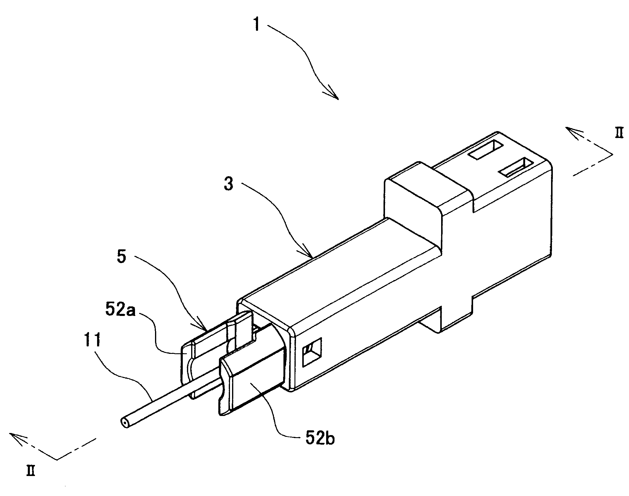
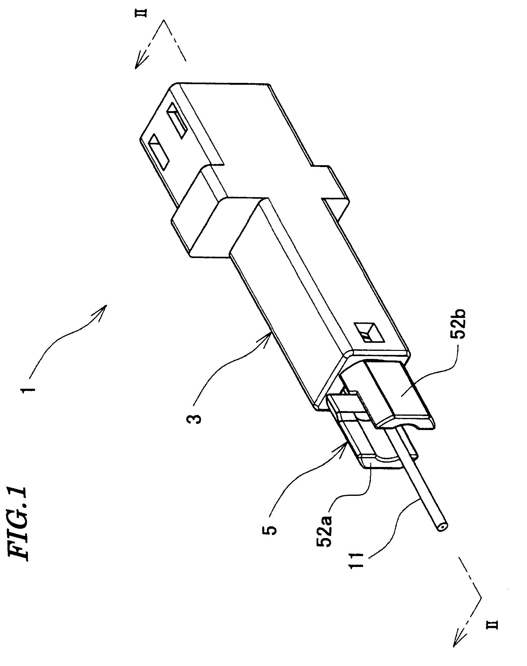
[0037]A description will be given of an optical connector 1 according to the present invention with reference to FIGS. 1 to 15.
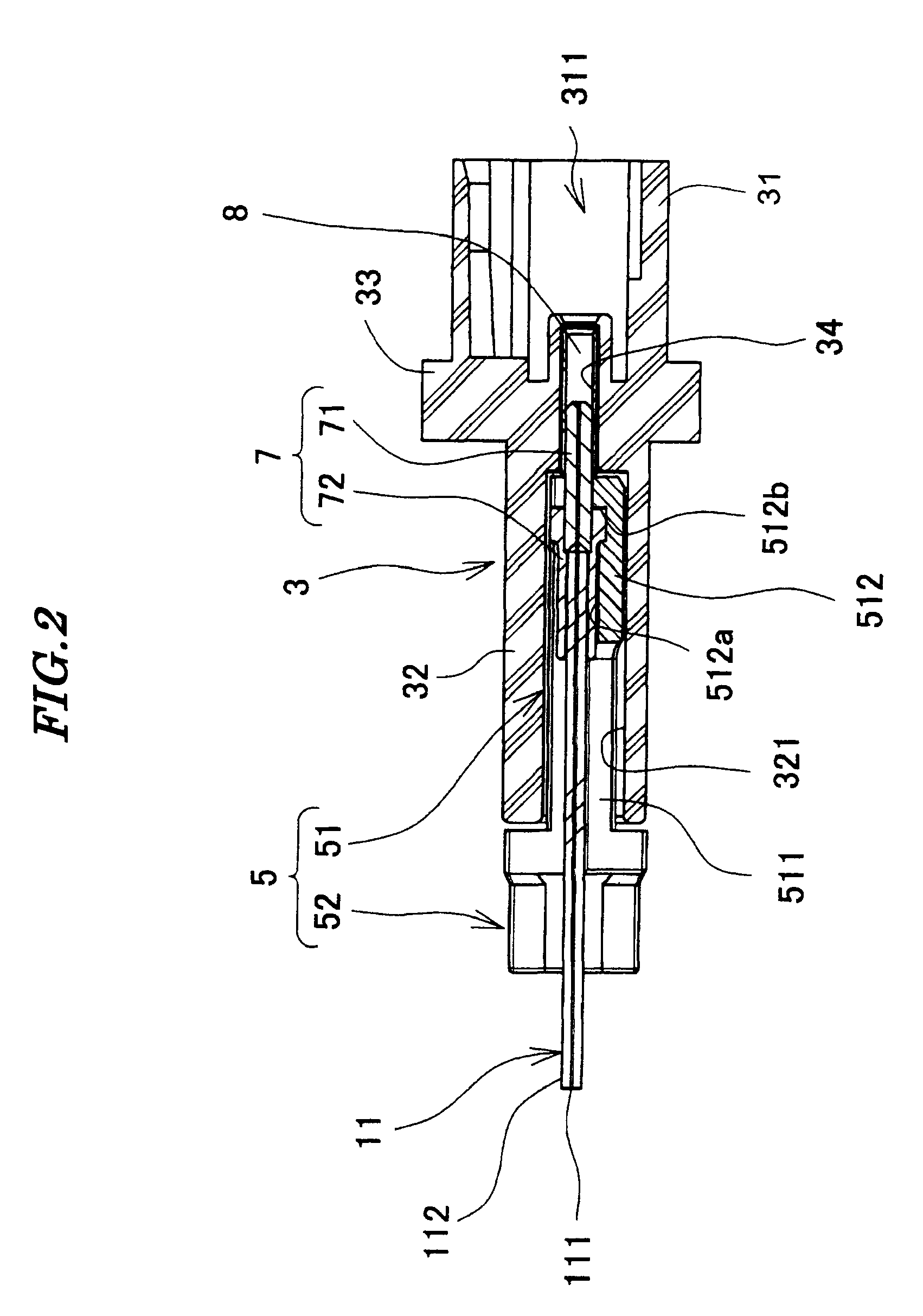
[0038]As shown in FIGS. 1 and 2, the optical connector 1 is comprised of a housing 3, a supporting member 5, a ferrule 7, and a divided sleeve 8.
[0039]As shown in FIGS. 2, 3, and 4, the housing 3 includes a fitting portion 31 and a supporting member-receiving portion 32. The fitting portion 31 is in the form of a box having an opening, and has a receiving space 311 (see FIG. 2). The receiving space 311 receives a front end portion of a mating housing of a mating optical connector, not shown. The fitting portion 31 has an upper surface formed with locking holes 312. When the mating housing is inserted into the receiving space 311, locking lugs (not shown) formed on the mating housing are engaged with the locking holes 312, whereby the mating housing is locked to the fitting portion 31.
[0040]The supporting member-receiving portion 32 is substantially hollow pr...
second embodiment
[0063]Next, a description will be given of an optical connector 201 according to the present invention with reference to FIGS. 16 to 18.
[0064]As shown in FIG. 16, a housing 203 of the optical connector 201 of the second embodiment is comprised of a fitting portion 231 and a supporting member-receiving portion 232. The fitting portion 231 and the supporting member-receiving portion 232 are joined by welding, gluing or the like. One end portion of the supporting member-receiving portion 232 opposite from the other end portion thereof toward the fitting portion 231 is formed with a male screw portion 2324. Screw threads of the male screw portion 2324 are omitted in FIG. 16.
[0065]A supporting member 205 is formed by a supporting member main body 251 and an operating portion 252. Component parts identical to those of the optical connector according to the first embodiment are designated by identical reference numerals, and detailed description thereof is omitted.
[0066]The supporting memb...
PUM
 Abstract
Description
Claims
Application Information
 - R&D
- Intellectual Property
- Life Sciences
- Materials
- Tech Scout
- Unparalleled Data Quality
- Higher Quality Content
- 60% Fewer Hallucinations
Browse by: Latest US Patents, China's latest patents, Technical Efficacy Thesaurus, Application Domain, Technology Topic, Popular Technical Reports.
© 2025 PatSnap. All rights reserved.Legal|Privacy policy|Modern Slavery Act Transparency Statement|Sitemap|About US| Contact US: help@patsnap.com


