
Input device

Inactive Publication Date: 2018-12-06
DENSO TEN LTD
View PDF7 Cites 1 Cited by
  • Summary
  • Abstract
  • Description
  • Claims
  • Application Information

AI Technical Summary

Benefits of technology

The patent text claims that the invention aims to make it easier to extend the wire from the vibrator that is attached to the back surface of the operation panel. The technical effect of this invention is to provide an input device and system where this is possible without causing any hindrances or difficulties in the process.

Problems solved by technology

Therefore, in the related art, in some cases it is difficult to draw out the wire from the vibrator.

Method used


Image

  • Input device
  • Input device
  • Input device

Examples


Embodiment Construction

[0019]Hereinafter, embodiments of an input device and an input system disclosed in the present invention will be described in detail with reference to accompanying drawings. The present invention is not limited to the embodiments described below.

1. Outline of Input Device

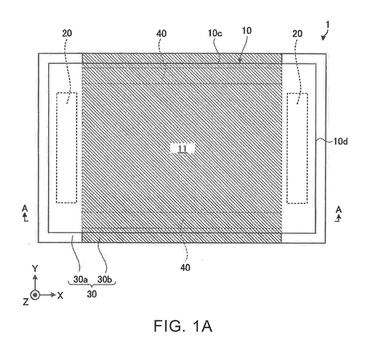
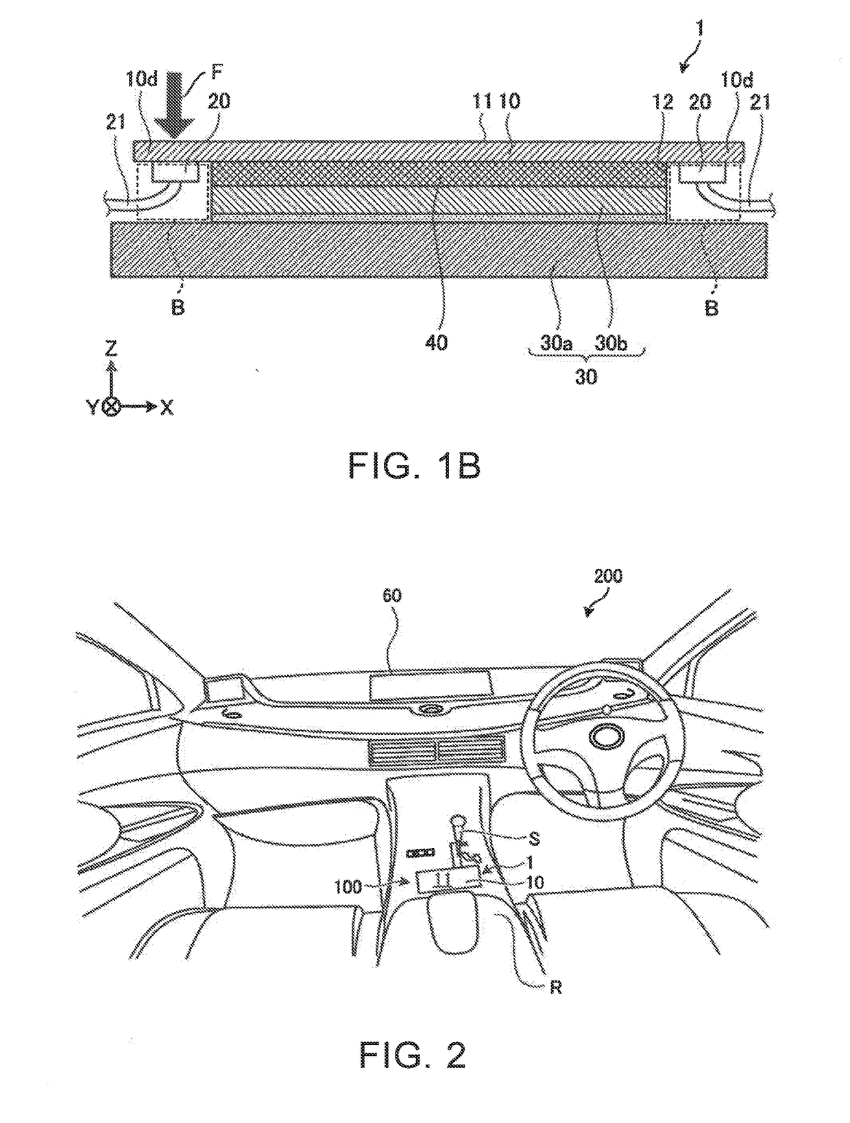
[0020]In the following, first, an outline of an input device according to an embodiment will be described using FIG. 1A and FIG. 1B. FIG. 1A is a plan view of an input device according to an embodiment. FIG. 1B is a cross sectional view taken along line A-A in FIG. 1A.

[0021]FIG. 1A and FIG. 1B, and the FIG. 4 and the subsequent figures are schematic views. Therefore, the size, shape, and the like of each constituent element shown in FIG. 1A and the like are not necessarily accurate. In each figure, in some cases each constituent element is shown in exaggeration for convenience of understanding. In FIG. 1A and FIG. 1B, a three-dimensional orthogonal coordinate system including an X axis, a Y axis and a Z axis is show...


PUM


Abstract

An input device includes an operation panel, a vibrator, and a support panel. The operation panel has an operation surface and a back surface. The vibrator is mounted on a mounting region of the operation panel at an end portion of the back surface, and vibrates the operation panel. The support panel faces the back surface of the operation panel, and supports the operation panel. The support panel includes a first support panel and a second support panel. The first support panel that, when viewed in a direction orthogonal to the operation surface, overlaps the mounting region of the operation panel on which the vibrator is mounted. The second panel is disposed between the operation panel and the first support panel, and when viewed in the direction orthogonal to the operation surface, does not overlap the mounting region of the operation panel on which the vibrator is mounted.

Description

BACKGROUND OF THE INVENTIONField of the Invention[0001]The present invention relates to an input device and an input system.[0002]Description of the Background Art[0003]In the related art, an input device that allows a riser to recognize acceptance of an input operation by giving a sense of touch to the user has been known. In the input device, for example, vibration is generated in response to a pressure force by the user acting on an operation surface, which allows the user to recognize acceptance of the input operation.[0004]Here, in the input device, a vibrator that vibrates an operation panel having an operation surface is mounted on the back surface of the operation panel. However, on a side of the back surface of the operation panel, a support panel for supporting the operation panel is disposed. For this reason, the vibrator is disposed between the support panel and the operation panel, and depending on a size of the support panel, a wire connected to the vibrator may come i...

Claims


Application Information

Patent Timeline
IPC IPC(8): G06F3/01
CPCG06F3/016
Inventor SHIROTO, HIRONORI
Owner DENSO TEN LTD
Learn More