Resonator element and resonator

Active Publication Date: 2010-08-12
SEIKO EPSON CORP
View PDF8 Cites 8 Cited by
  • Summary
  • Abstract
  • Description
  • Claims
  • Application Information

AI Technical Summary

Benefits of technology

[0010]According to the configuration, the wiring line coupled to the upper electrode is drawn out to the second surface through the side surfaces of the resonating arm from the first surface so as to surround the resonating arm. The wiring line is drawn out from the first surface to the second surface, which is the back surface of the first surface. Thus, it is possible to easily draw out the wiring line to the back surface. Since the front and back surfaces of the resonator element can be utilized for the arrangement of wiring line, an area that can be used for the arrangement of wiring line is increased. As a result, the degree of arrangement freedom of the wiring line is increased. Further, the wiring line can be arranged in a limited space, being able to achieve miniaturization of the resonator element.
[0022]According to the configuration, since the above-described resonator element is housed in the container, it is possible to miniaturize the resonator element. As a result, it is possible to provide a miniaturized resonator element.

Problems solved by technology

Therefore, the arrangement of wiring lines becomes complex and a large area is required for the arrangement.
In the configuration disclosed in the example, the area of the resonator element decreases and it becomes hard to ensure wiring paths especially when the resonator needs to be downsized.
As a result, it is hard to realize the miniaturization of the resonator element.

Method used


Image

  • Resonator element and resonator
  • Resonator element and resonator
  • Resonator element and resonator

Examples


first embodiment

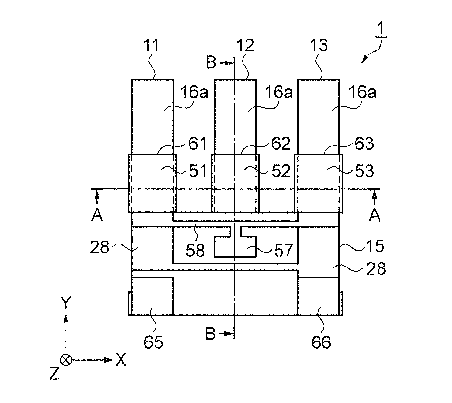
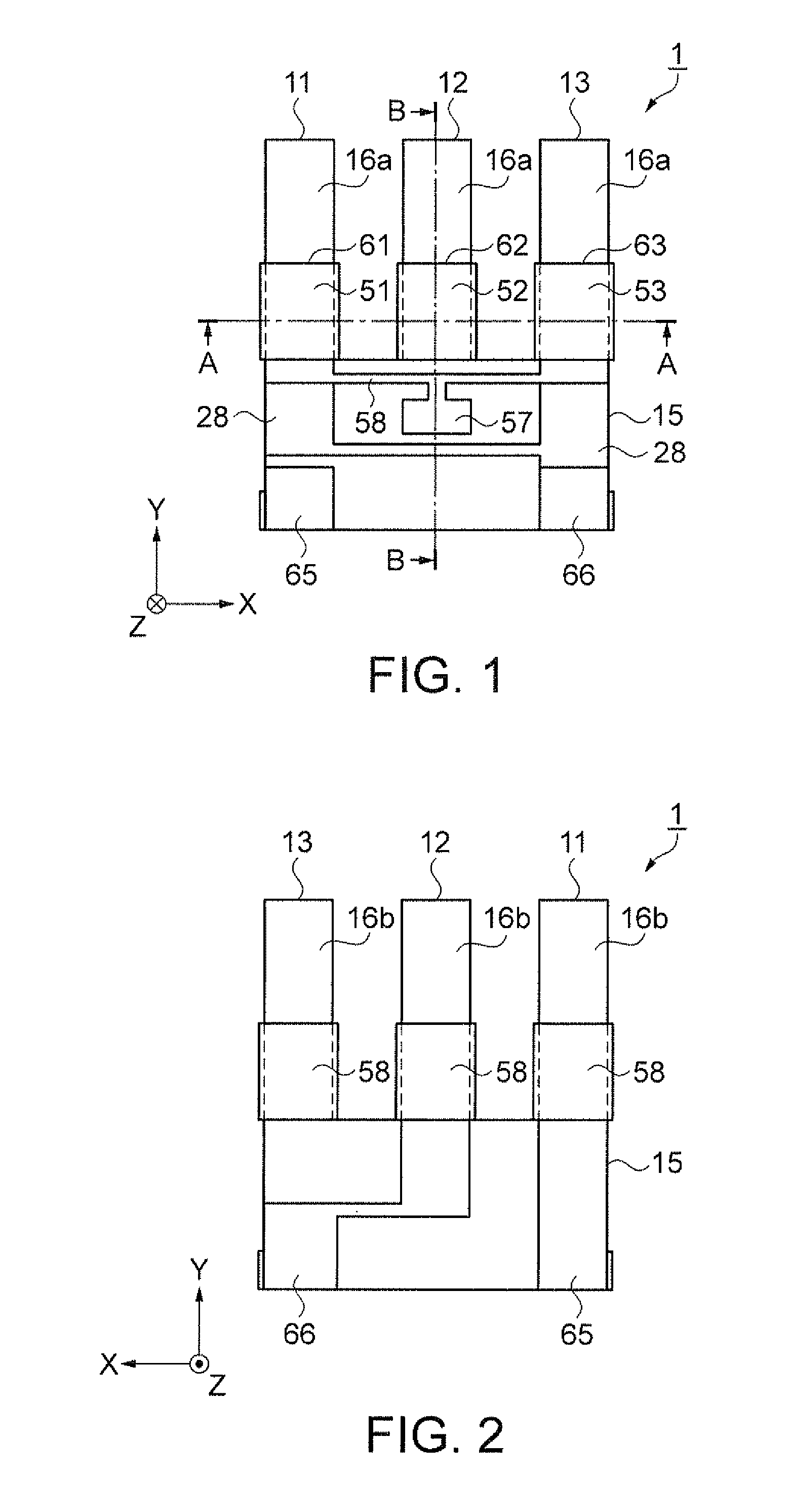
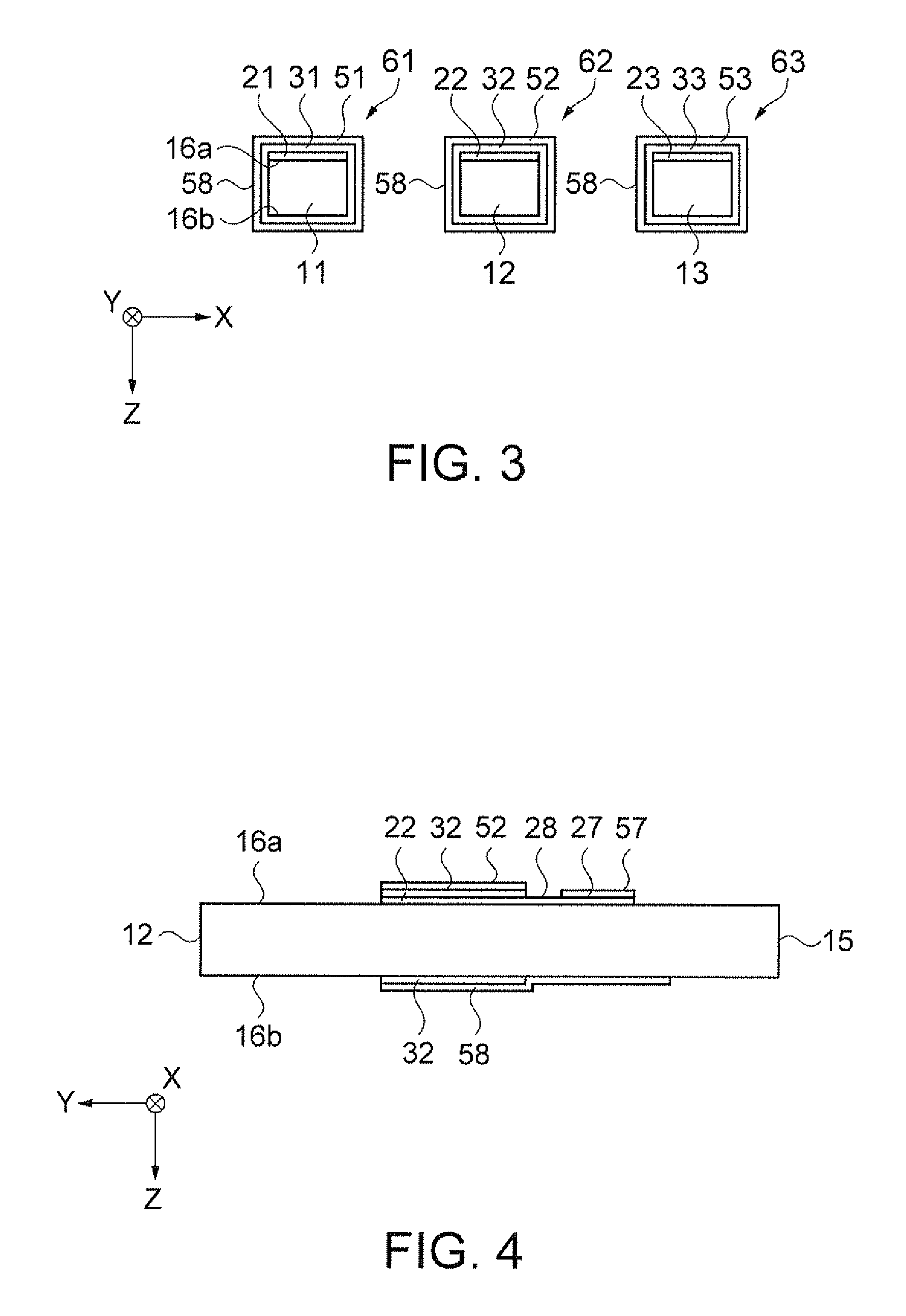
[0041]FIG. 1 is a schematic plan view showing a configuration of a resonator element according to a first embodiment. FIG. 2 is a schematic plan view showing a configuration of a back surface of the resonator element of FIG. 1. FIG. 3 is a schematic sectional view taken along the line A-A of FIG. 1, and shows a configuration of piezoelectric elements. FIG. 4 is a schematic sectional view taken along the line B-B of FIG. 1.

[0042]As shown in FIGS. 1 and 2, a resonator element 1 is formed by employing a base material such as quartz crystal or silicon. The resonator element 1 is in a manner such that a thickness direction thereof is in a Z-direction when the resonator element 1 is developed in an XY-plane in an orthogonal coordinate system. The resonator element 1 has three resonating arms 11, 12, and 13 arranged in an X-direction while extending in parallel with one another in a Y-direction. The resonating arms 11, 12, and 13 are connected to a base 15, so that the resonator element 1 ...

second embodiment

[0077]A resonator element according to a second embodiment will be described. In the present embodiment, an arrangement of wiring lines respectively coupled to the upper electrodes and the lower electrodes is different from that of the first embodiment.

[0078]FIG. 9 is a schematic plan view showing a configuration of a resonator element according to the embodiment. FIG. 10 is a schematic plan view showing a configuration of a back surface of the resonator element of FIG. 9. FIG. 11 is a schematic sectional view taken along the line C-C of FIG. 9, and shows a configuration of piezoelectric elements. FIG. 12 is a schematic sectional view taken along the line D-D of FIG. 9.

[0079]As shown in FIGS. 9 and 10, a resonator element 2 is formed by employing a base material such as quartz crystal or silicon. The resonator element 2 is in a manner such that a thickness direction thereof is in the Z-direction when the resonator element 2 is developed in an XY-plane in an orthogonal coordinate sys...

third embodiment

[0114]As a third embodiment, a resonator equipped with the above-described resonator element will be described.

[0115]FIGS. 16A and 16B show a configuration of the resonator. FIG. 16A is a schematic plan view while FIG. 16B is a schematic sectional view taken along the line G-G of FIG. 16A.

[0116]A resonator 5 includes the resonator element 1, a ceramic package 81 serving as a container, and a lid 85.

[0117]The ceramic package 81 has a recess for housing the resonator element 1. In the recess, a connection pad 88 coupled to the mounting electrodes of the resonator element 1 is provided. The connection pad 88 is coupled to a wiring line in the ceramic package 81, and conductively coupled to an external connection terminal 83 provided to an outer periphery of the ceramic package 81.

[0118]On a periphery of the recess of the ceramic package 81, a seam ring 82 is provided. Further, a through-hole 86 is provided at a bottom of the ceramic package 81.

[0119]The resonator element 1 is bonded an...


PUM


Abstract

A resonator element includes: three or more resonating arms, each of the resonating arms including; a lower electrode provided on a first surface of the resonating arm, a piezoelectric film formed on the lower electrode, an upper electrode formed on the piezoelectric film, a first wiring line coupled to the lower electrode, and a second wiring line coupled to the upper electrode; and a base to which the resonating arms are connected. In the resonator element, the resonating arm vibrates in a thickness direction of the resonating arm. The resonating arms adjacent to each other vibrate in opposite directions from each other. The first surface is opposed to a second surface in the thickness direction. The second wiring line is drawn out to the second surface through side surfaces of the resonating arm so as to surround the resonating arm.

Description

BACKGROUND[0001]1. Technical Field[0002]The present invention relates to a resonator element having resonating arms, and a resonator.[0003]2. Related Art[0004]In a resonator having a resonating arm, a resonator element is known in which the resonating arm vibrates in a thickness direction thereof in addition to one in which the resonating arm vibrates in a plane as flexural vibrations. The resonator element generally has a plurality of resonating arms so as to perform walk-mode vibration in which the resonating arms adjacent to each other alternatively vibrate in opposite directions from each other.[0005]JP-A-2008-224627 is an example of related art. The example discloses an angular velocity sensor using the walk-mode vibration. The angular velocity sensor has three arms (resonating arms) formed of silicon, for example. On one surface of each arm, a lower-layer electrode (lower electrode), a piezoelectric thin film (piezoelectric film), and an upper-layer electrode (upper electrode)...

Claims


Application Information

Patent Timeline
IPC IPC(8): H01L41/02
CPCH03H9/0509H03H9/21H03H9/1021
Inventor ISHII, MASAHIROFUNAKAWA, TAKEO
Owner SEIKO EPSON CORP
Why Eureka
Try Eureka