Home Surveillance Device

a home surveillance and home technology, applied in closed circuit television systems, peepholes, television systems, etc., can solve the problems of limited vision field of peepholes, inconvenient use of conventional peepholes, and user inability to watch visitors

a home surveillance and home technology, applied in closed circuit television systems, peepholes, television systems, etc., can solve the problems of limited vision field of peepholes, inconvenient use of conventional peepholes, and user inability to watch visitors

US20130016211A1Inactive Publication Date: 2013-01-17BRINNO

Image

  • Home Surveillance Device
  • Home Surveillance Device
  • Home Surveillance Device

Examples


Embodiment Construction

[0026]The home surveillance device of the present invention is described in detail in cooperation with the drawings below. The specification of the present invention discloses two embodiments, which are different in the functions of the module boards. Thereinafter, the connection method of the external structure of the present invention is described beforehand. Then are described the differences of the two embodiments.

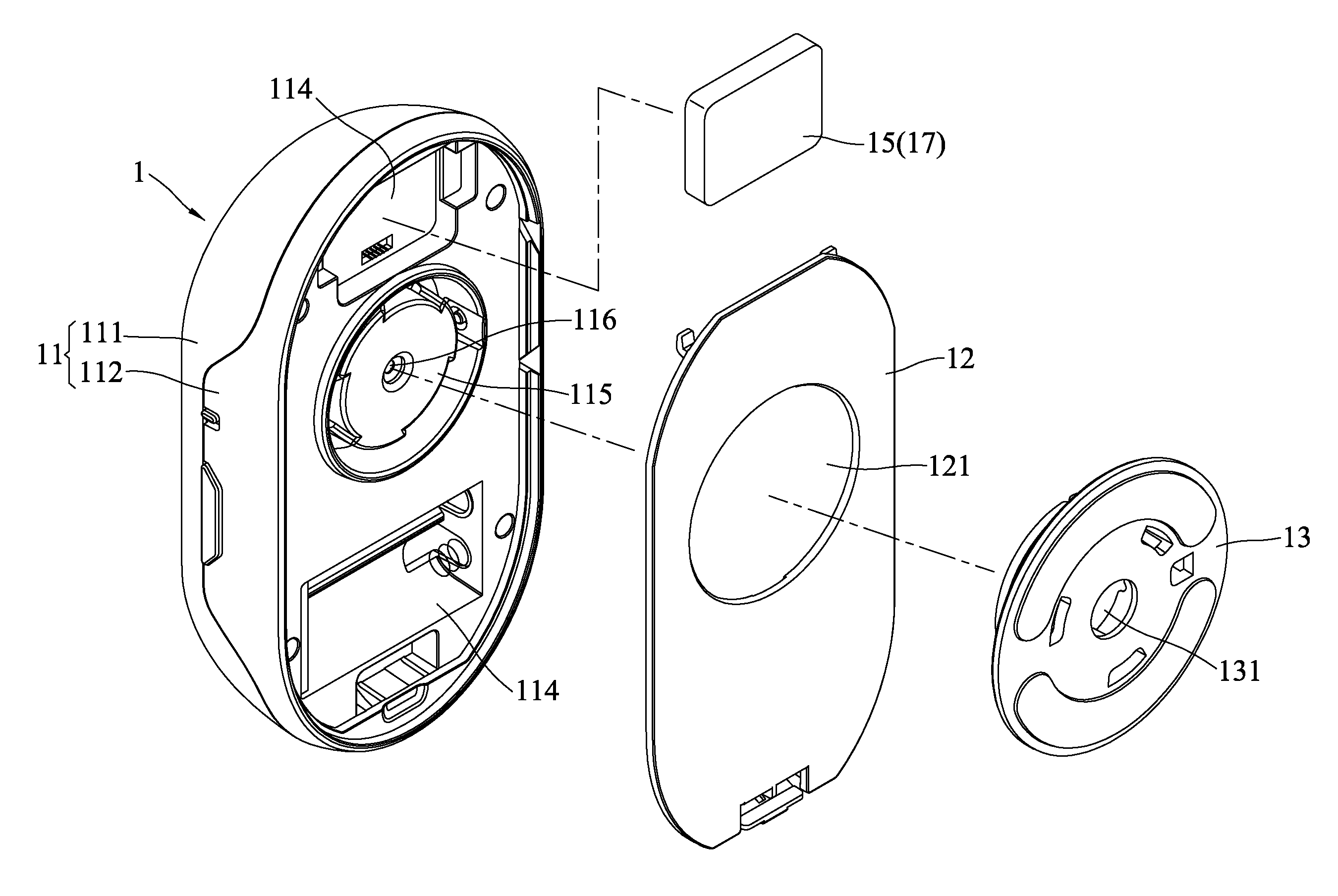
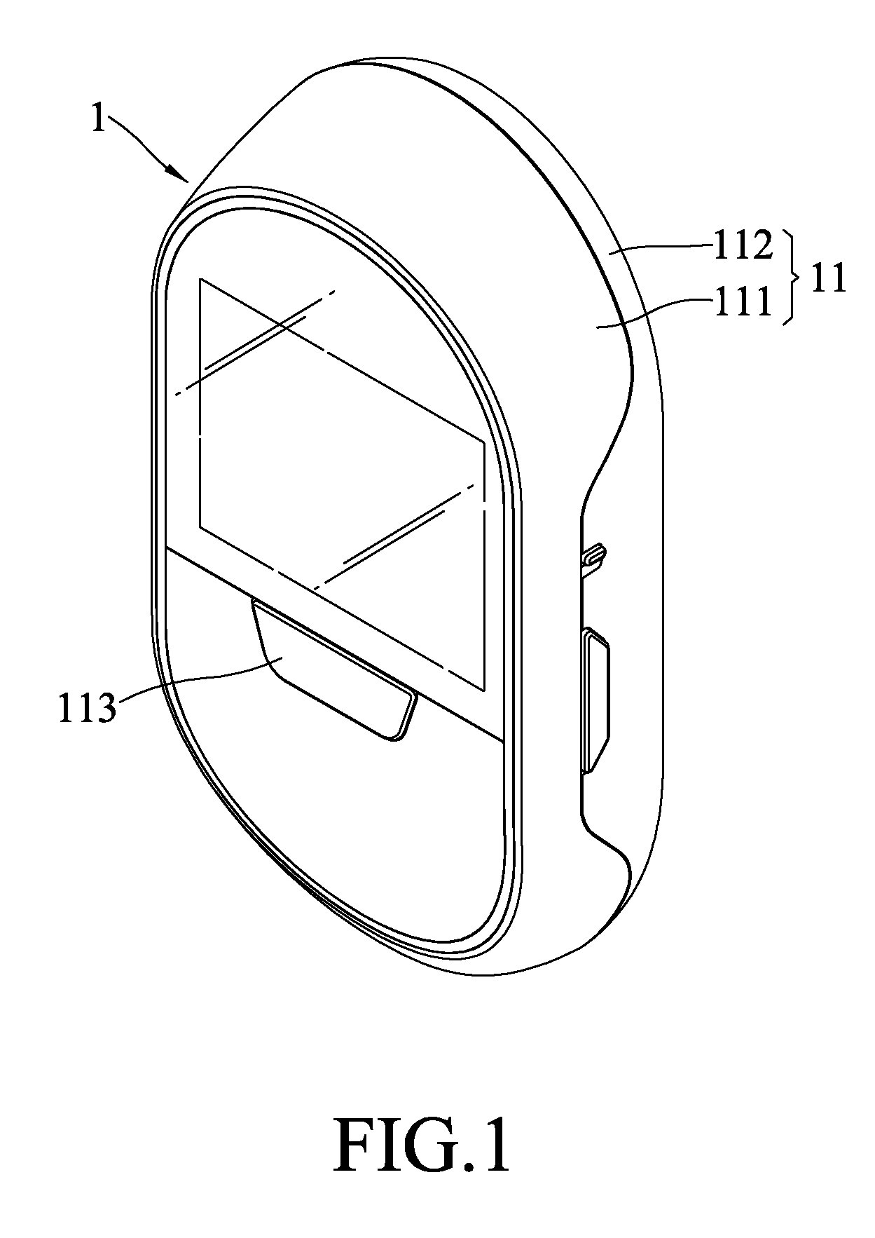
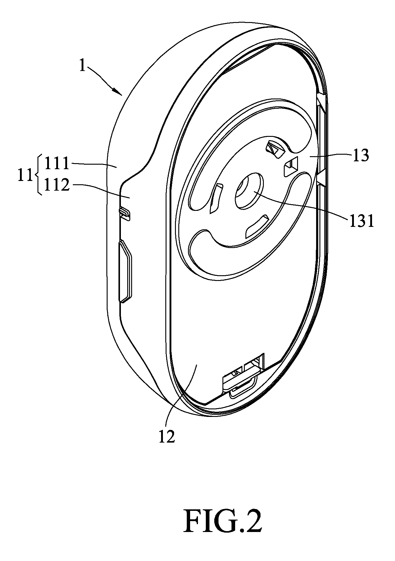
[0027]Refer to FIG. 1 and FIG. 2 respectively a front perspective view and a rear perspective view of a home surveillance device according to one embodiment of the present invention. Also refer to FIG. 3 and FIG. 4 respectively a perspective exploded view of the structure disclosed in FIG. 2 and a perspective exploded view wherein some components are not shown. The basic structure of the home surveillance device is described herein. The home surveillance device of the present invention comprises a body 1, a cover board 12, and a plate-like member 13, a module board 14,...


PUM


Abstract

A home surveillance device comprises a body, a module board, a vibration sensation module, a power supply module, a cover board, and a plate-like member. The body includes a housing having a first casing with a control interface and a second casing containing at least one accommodation space, an assembly member and a casing through-hole. The module board is arranged inside the housing and includes an image-capture module, a display module, a driving module, a microprocessor, a register module, a memory card module, and an I / O module. The vibration sensation module is arranged in the accommodation space. The power supply module connects with the module board and supplies power to the system. The cover board has an assembly through-hole and is assembled to the second casing and opposite to the first casing. The plate-like member has a plate through-hole and is assembled to the assembly member via the assembly through-hole.

Description

BACKGROUND OF THE INVENTION[0001]1. Field of the Invention[0002]The present invention relates to a home surveillance device, particularly to a home surveillance device triggered by vibration or temperature.[0003]2. Description of the Related Art[0004]No matter whether one's residence is in a townhouse, an apartment, or a mansion, the door thereof normally has a peephole. When a visitor rings the doorbell or knocks the door, the resident can examine the visitor via the peephole before he decides whether to open the door. However, the conventional peephole provides limited vision field. Further, the user cannot watch the visitor unless his eye approaches the peephole. Therefore, the conventional peephole is somewhat inconvenient for the user.[0005]Thus, there are digital peephole devices developed to solve the problems of the conventional peephole, wherein the lens captures the image of the visitor, and wherein the user identifies the visitor or the external status via the image prese...

Claims


Application Information

Patent Timeline
17 Jan 2013
Publication
US20130016211A1
IPC
H04N7/18
CPC
E06B7/30; H04N5/232; H04N7/186; H04N5/2251; H04N23/50; H04N23/60
Inventors
YEH, MIN-HSIUNG