

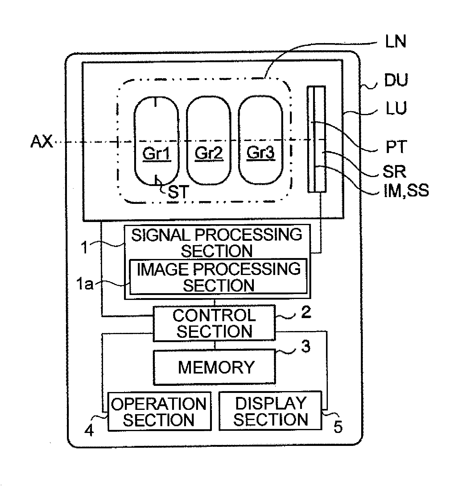
Imaging Lens, Imaging Optical Device, and Digital Equipment
a technology for imaging optical devices and lenses, applied in the field of imaging optical devices, imaging lens systems, digital appliances, can solve the problems of affecting image quality, unfavorable compactness of the lens unit as a whole, and challenging to achieve both, and achieve compact addition of high-performance image input capability, correcting chromatic and spherical aberration, and improving image quality
- Summary
- Abstract
- Description
- Claims
- Application Information
AI Technical Summary
Benefits of technology
Problems solved by technology
Method used
Image

Examples
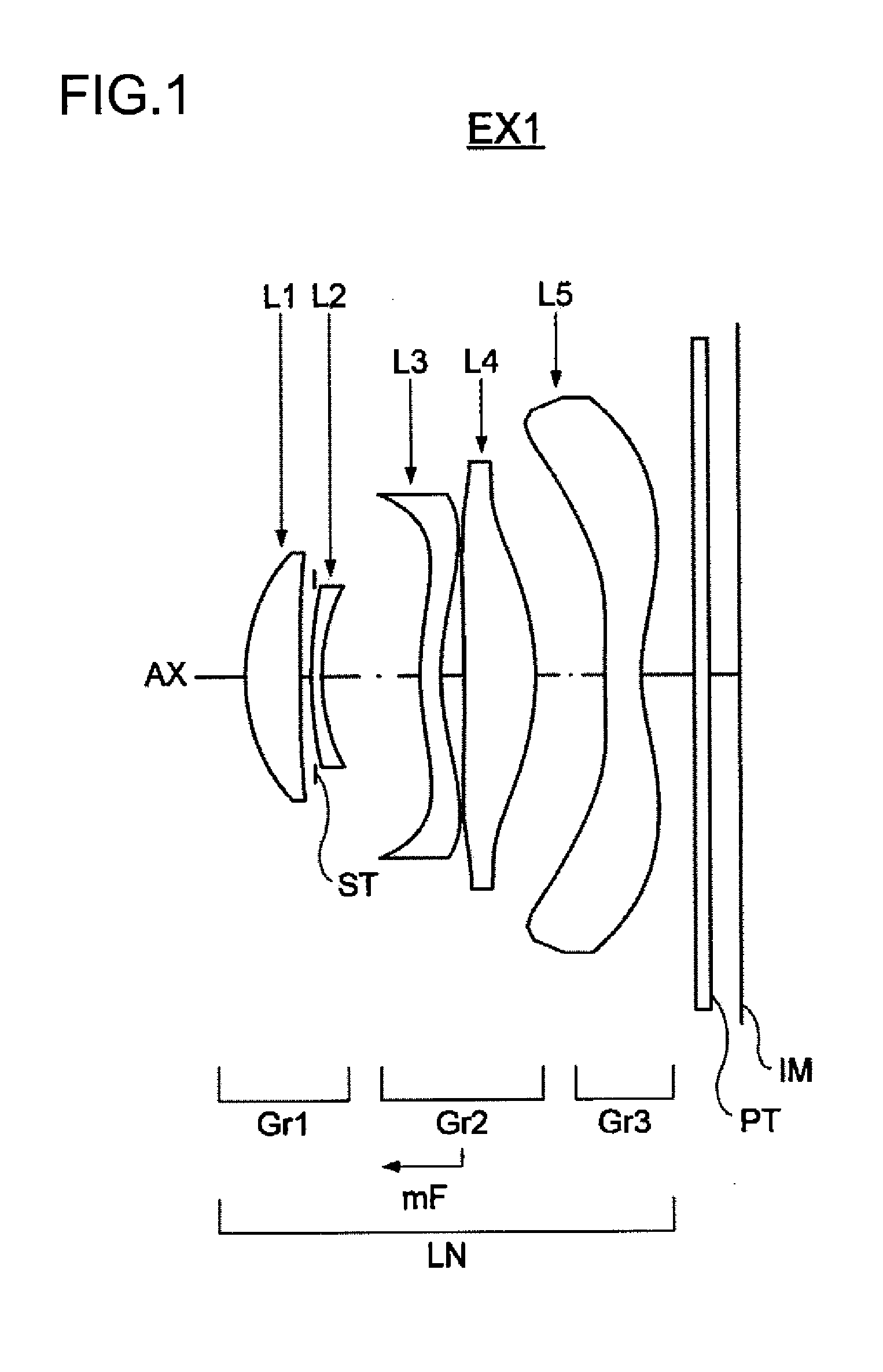
example 1
[0308]
Unit: mmSurface DataSurface No.rdndvdObject Surface∞∞ 1*1.5120.5321.5447056.15 2*−96.0430.140 3 (Aperture)∞−0.033 4*3.5480.1001.6320023.41 5*1.5630.950 6*2.2000.2001.5447056.15 7*1.8800.229 8*−16.8960.6891.5457744.11 9*−2.0430.66710*4.9020.3501.5304855.7211*1.3740.51212∞0.1451.5163364.1413∞0.300Image Surface∞Aspherical Surface DataSurface 1K =9.3784e−002A4 =−6.5748e−003A6 =1.0845e−002A8 =−1.9588e−002A10 =1.1876e−002A12 =0.0000e+000A14 =0.0000e+000A16 =0.0000e+000Surface 2K =−5.0000e+001A4 =6.7283e−002A6 =−6.4351e−002A8 =5.0700e−002A10 =−1.5895e−002A12 =0.0000e+000A14 =0.0000e+000A16 =0.0000e+000Surface 4K =−4.3891e+000A4 =1.6290e−002A6 =2.5460e−002A8 =−1.7945e−002A10 =6.0302e−003A12 =−7.8364e−003A14 =0.0000e+000A16 =0.0000e+000Surface 5K =−3.1760e+000A4 =5.9008e−002A6 =9.6928e−002A8 =−4.8324e−002A10 =−3.3744e−002A12 =6.7187e−002A14 =0.0000e+000A16 =0.0000e+000Surface 6K =−7.7945e+000A4 =−6.6004e−002A6 =−6.9701e−003A8 =−5.3030e−004A10 =−2.1910e−003A12 =−1.0291e−004A14 =0.0000e+...
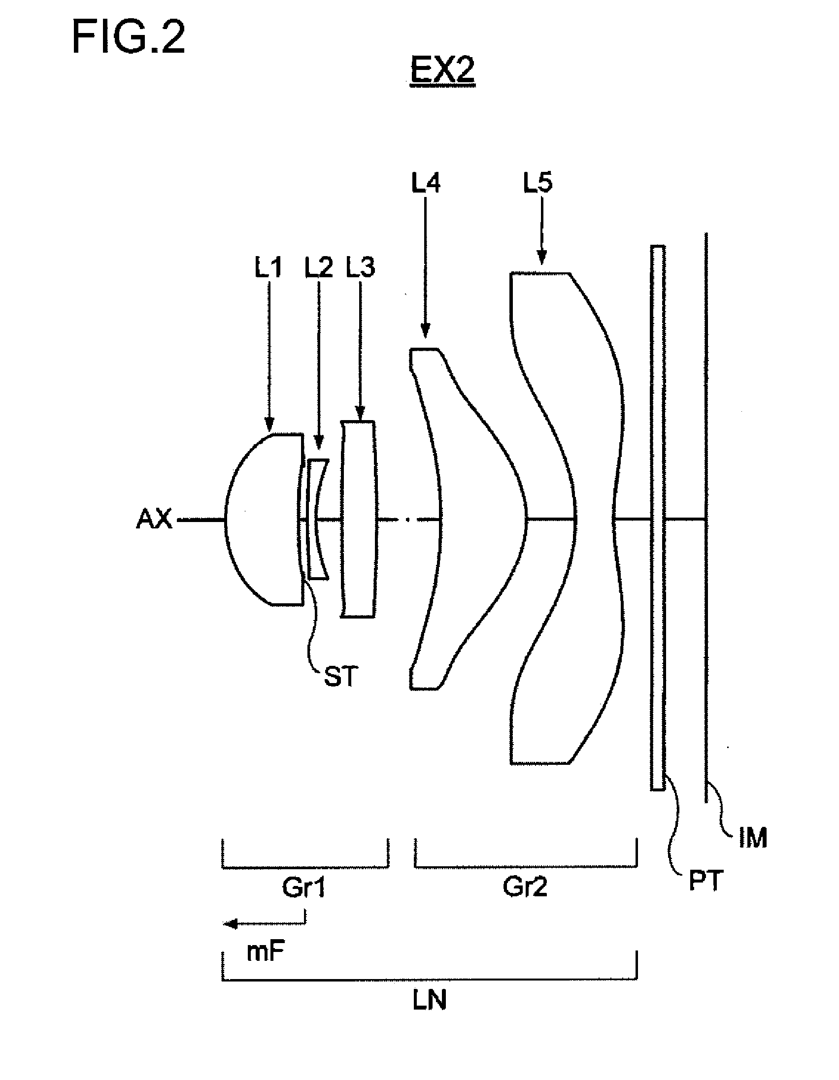
example 2
[0309]
Unit: mmSurface DataSurface No.rdndvdObject Surface∞∞ 1*1.5710.8751.5447056.15 2*15.1890.055 3 (Aperture)∞0.050 4*7.8240.1001.6320023.41 5*1.9500.308 6*40.3120.4121.6320023.41 7*−17.1710.761 8*−5.6111.0211.5447056.15 9*−1.4020.58410*−2.4230.4501.5447056.1511*3.4710.44012∞0.1451.5163364.1413∞0.500Image Surface∞Aspherical Surface DataSurface 1K =8.3130e−001A4 =−1.0268e−002A6 =−4.2689e−003A8 =−4.3147e−003A10 =4.2401e−003A12 =−2.4172e−003A14 =−7.5305e−004A16 =0.0000e+000Surface 2K =6.8651e+001A4 =8.9811e−002A6 =−2.9703e−002A8 =6.1974e−002A10 =−1.1922e−002A12 =2.5853e−002A14 =1.7162e−002A16 =0.0000e+000Surface 4K =−7.0000e+001A4 =−5.6006e−002A6 =1.0710e−001A8 =−1.7971e−001A10 =8.7586e−002A12 =−2.3393e−003A14 =9.7877e−005A16 =0.0000e+000Surface 5K =−8.8402e+000A4 =3.9474e−002A6 =7.2314e−002A8 =−1.2762e−001A10 =9.1917e−002A12 =−2.7951e−002A14 =2.6160e−004A16 =0.0000e+000Surface 6K =7.0000e+001A4 =−5.2533e−003A6 =−3.9345e−003A8 =2.2647e−002A10 =−9.9634e−003A12 =6.7941e−003A14 =−5.7345...
example 3
[0310]
Unit: mmSurface DataSurface No.rdndvdObject Surface∞∞ 1*1.4100.4561.5447056.15 2*10.0000.055 3 (Aperture)∞0.060 4*4.9700.1011.6320023.41 5*2.1000.573 6*−4.6020.6791.5447056.15 7*−2.2490.309 8*−1.0970.5581.5447056.15 9*−1.0120.98810*−3.9200.1511.5447056.1511*3.4400.92512∞0.1451.5163364.1413∞0.100Image Surface∞Aspherical Surface DataSurface 1K =1.1862e+000A4 =−2.6373e−002A6 =−3.7904e−002A8 =7.6044e−003A10 =−3.6277e−002A12 =4.8617e−002A14 =−7.4729e−002A16 =0.0000e+000Surface 2K =−5.0000e+001A4 =3.0971e−002A6 =5.9684e−004A8 =8.0563e−002A10 =−9.6559e−002A12 =3.0944e−002A14 =1.0028e−001A16 =0.0000e+000Surface 4K =1.3839e+001A4 =−2.7610e−002A6 =6.0322e−002A8 =−1.2309e−001A10 =1.0005e−001A12 =−6.2515e−002A14 =−7.3769e−002A16 =0.0000e+000Surface 5K =−1.2066e+000A4 =4.5407e−002A6 =9.3364e−002A8 =−1.8448e−002A10 =−6.2809e−002A12 =1.1871e−001A14 =−1.2456e−002A16 =0.0000e+000Surface 6K =1.7748e+001A4 =−1.2819e−002A6 =−3.9045e−002A8 =5.5413e−002A10 =−8.3289e−003A12 =−4.4816e−002A14 =4.3030e...
PUM
 Abstract
Description
Claims
Application Information