Pedometer for shoe

a pedometer and shoe technology, applied in the direction of distance measurement, instruments, fastenings, etc., can solve the problems of not being able to separate the number of running steps and the number of walking steps of a portable pedometer and a conventional pedometer mounted on a sho

Inactive Publication Date: 2013-01-31
OSHIO KOZO
View PDF6 Cites 21 Cited by
  • Summary
  • Abstract
  • Description
  • Claims
  • Application Information

AI Technical Summary

Problems solved by technology

A conventional portable pedometer and a conventional pedometer mountable on a shoe have never been able to separately measure the number of walking steps and the number of running steps.

Method used


Image

  • Pedometer for shoe
  • Pedometer for shoe
  • Pedometer for shoe

Examples


Embodiment Construction

[0077]Hereinafter, some embodiments of the present invention will be described. The embodiments do not limit the invention according to the claims, and all the combinations of the features described in the embodiments are not necessarily essential to means provided by aspects of the invention.

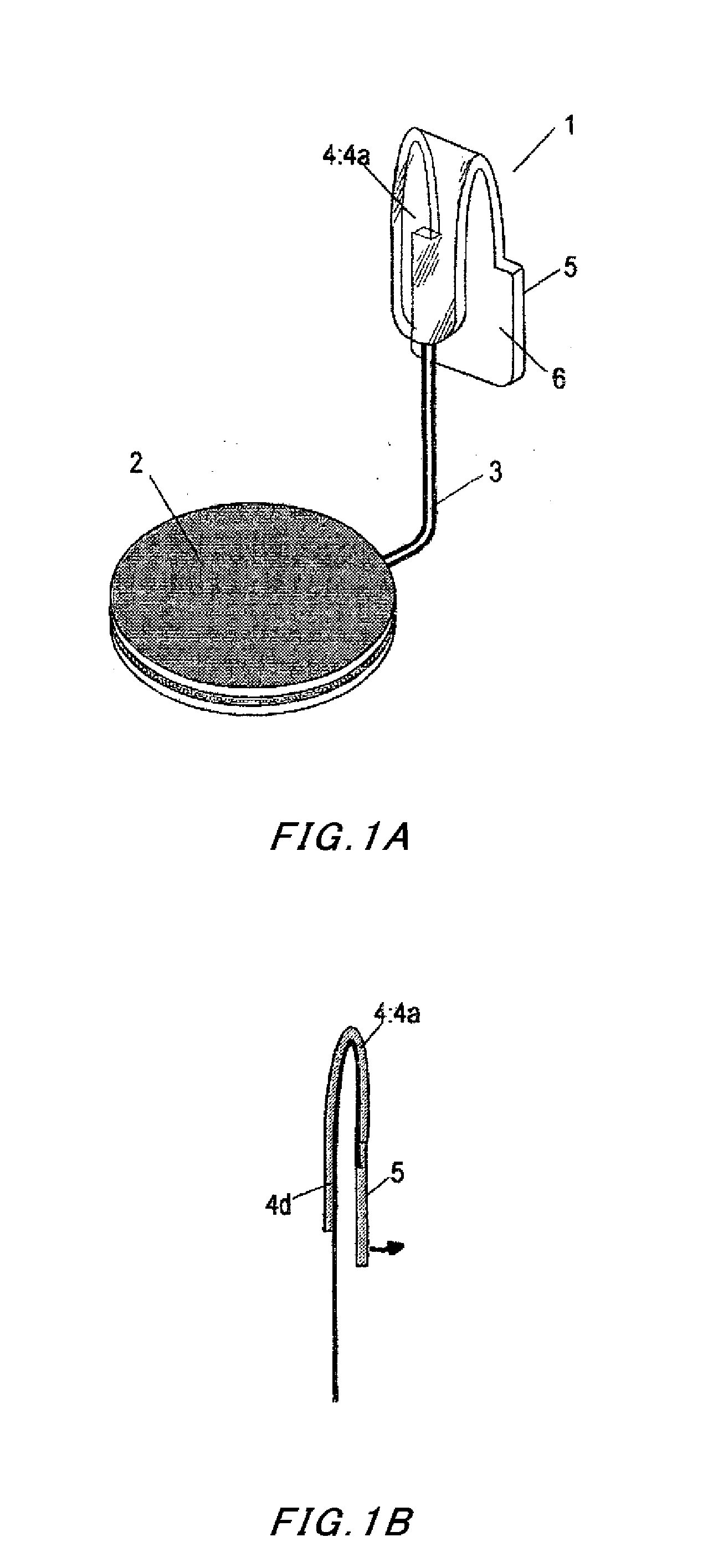
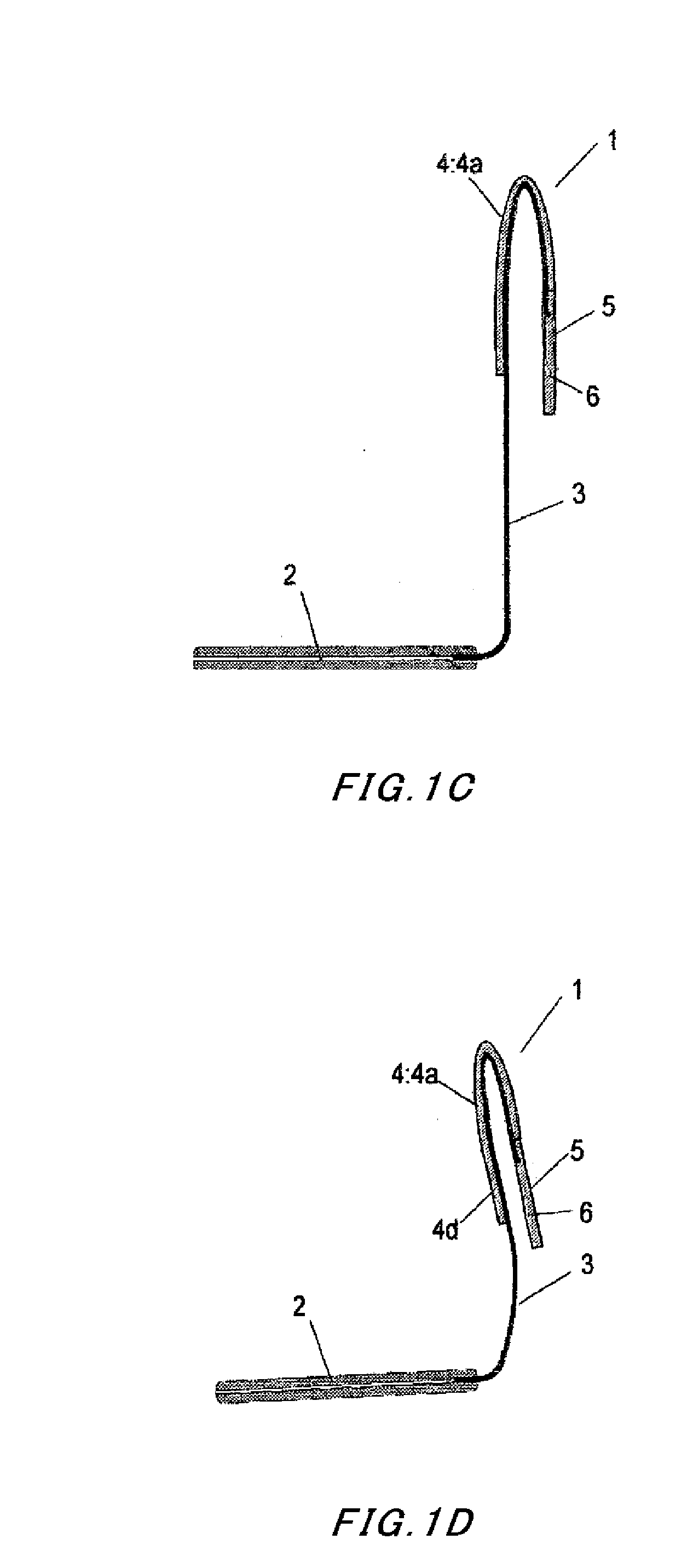
[0078]The following describes in detail exemplary embodiments of the present invention with reference to the attached drawings. FIGS. 1A to 1D and FIGS. 2A to 2D are overall views illustrating exemplary embodiments of the pedometer for a shoe according to the present invention. FIGS. 3A to 3D illustrate exemplary embodiments of an electromotive unit of the pedometer for a shoe according to the present invention.

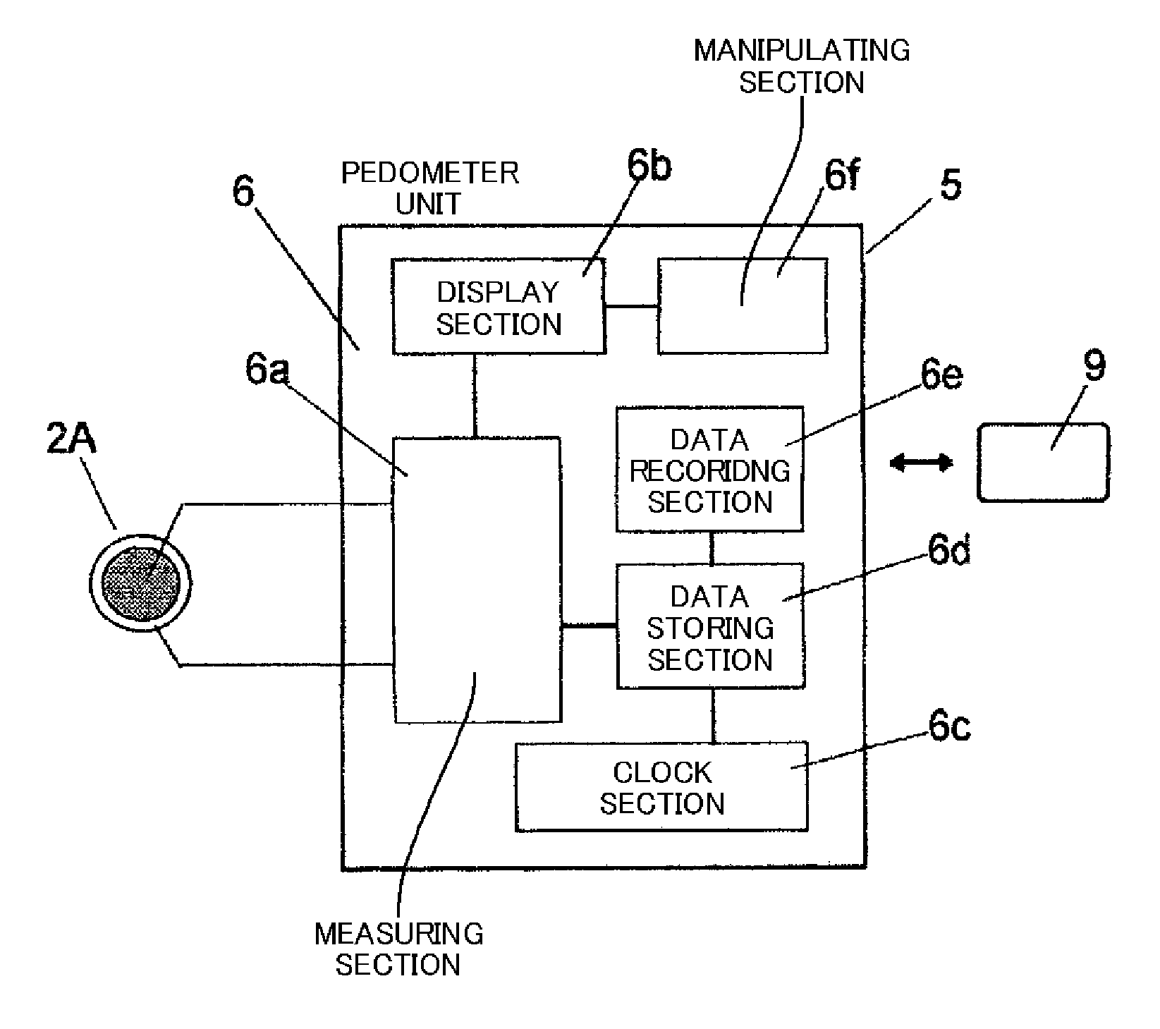
[0079]Referring to FIGS. 1A to 1D, an electromotive unit 2 is shaped like a flat plate to have a substantially circular outline. A wire material 3 is connected to the electromotive unit 2 and configured to deliver the electric current produced by the electromotive unit 2. The wire materi...


PUM


Abstract

An electromotive unit that produces an electric current in response to a pressure applied thereto when a user lands the ground on his / her foot while walking or running, or a pressure detector that detects variation in the applied pressure is formed like a flat plate and arranged within a small space in a shoe. A wire material is provided to deliver, outside the shoe, the electric current produced in response to the pressure applied when the user lands the ground on his / her foot or a signal indicative of the variation in the applied pressure. The wire material is connected to a pedometer unit outside the shoe to perform counting. The wire material can be fixed and mounted onto a desired portion in the opening of the shoe by using a fastener or by being formed as a fixable wire material.

Description

BACKGROUND[0001]1. Technical Field[0002]The present invention relates to a pedometer for a shoe that is mountable on a ready-made shoe to detect steps during walking and running and to measure the number of walking and running steps.[0003]2. Related Art[0004]In the conventional art, a pedometer has been proposed which can be attached onto a body of a user and measures the number of steps while the user walks by detecting the movement of the body. The movement of the body, however, includes a variety of other ways of movement than walking. Therefore, the conventional pedometer may erroneously detect the movement of the body while the user is not walking, which may result in erroneous measurements. To eliminate such measurement errors, Japanese Utility Model Application Publication No. 05-093209 discloses an invention of measuring the number of steps based on detection of output from a piezoelectric element, for example.[0005]The above-mentioned invention has encountered a problem. Ac...

Claims


Application Information

Patent Timeline
Patent Type & Authority Applications(United States)
IPC IPC(8): G01C22/00
CPCA43B3/0005G01C22/006A43C19/00A43B3/34
Inventor OSHIO, KOZO
Owner OSHIO KOZO
Why Eureka
Try Eureka