Molded article and venting assembly for a rotating mold

a technology of rotating molds and venting assemblies, which is applied in the direction of dough shaping, application, manufacturing tools, etc., can solve the problems of negative affecting the aesthetic appearance or, possibly, and the fatigue durability of finished articles

Active Publication Date: 2013-02-28
MICHELIN RECH & TECH SA +1
View PDF8 Cites 57 Cited by
  • Summary
  • Abstract
  • Description
  • Claims
  • Application Information

AI Technical Summary

Benefits of technology

[0007]In an exemplary embodiment of the molded article, the variation off the edge radius is defined by a set of decreasing radii at circumferential locations between the midpoint between a pair of adjacent web spokes and at least one of the adjacent web spokes. In a yet another embodiment the variation of said edge radius is defined by a plurality control radii. The plurality of control radii may comprise a first control radius at a circumferential location corresponding to a mid point between a pair of adjacent web spokes, a second control radius at a circumferential location circumferentially adja

Problems solved by technology

In either case, the entrapped air can form small bubbles which negatively affect the aesthetic appearance or, possibly, the fatigue durability of the finis

Method used


Image

  • Molded article and venting assembly for a rotating mold
  • Molded article and venting assembly for a rotating mold
  • Molded article and venting assembly for a rotating mold

Examples


Embodiment Construction

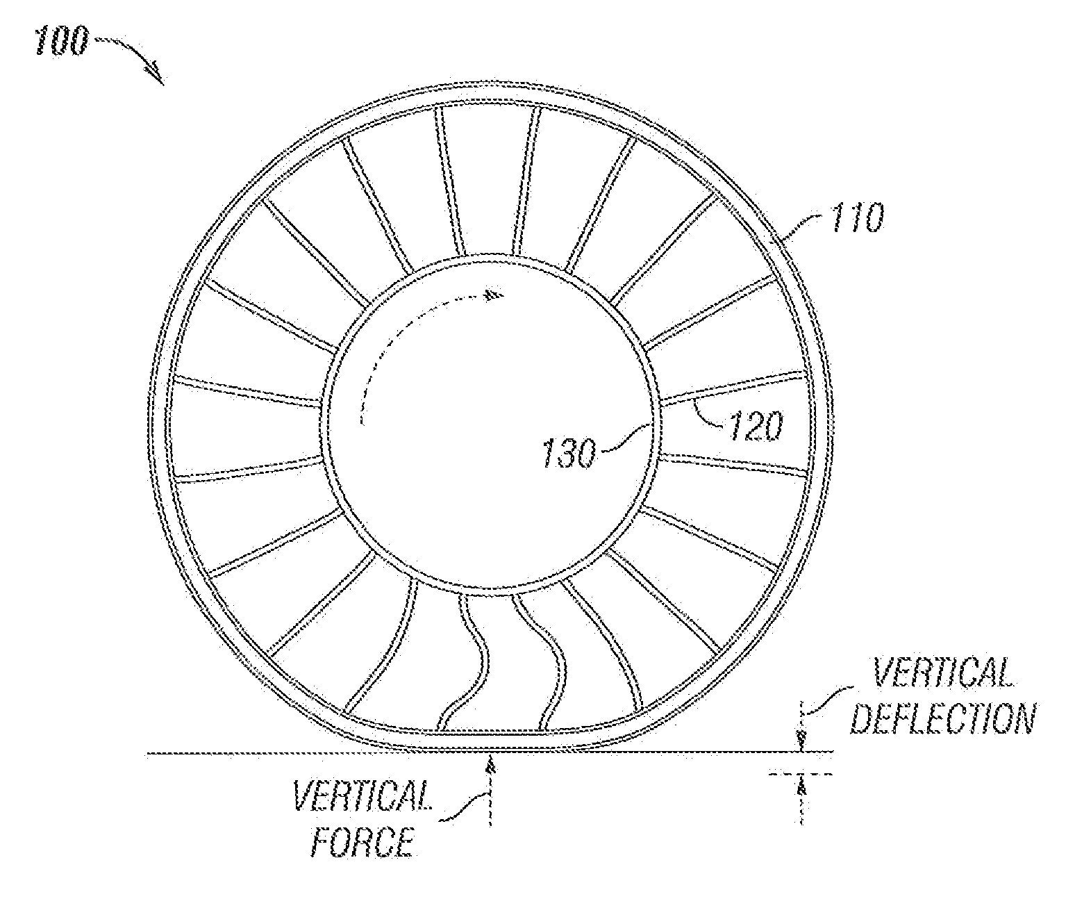
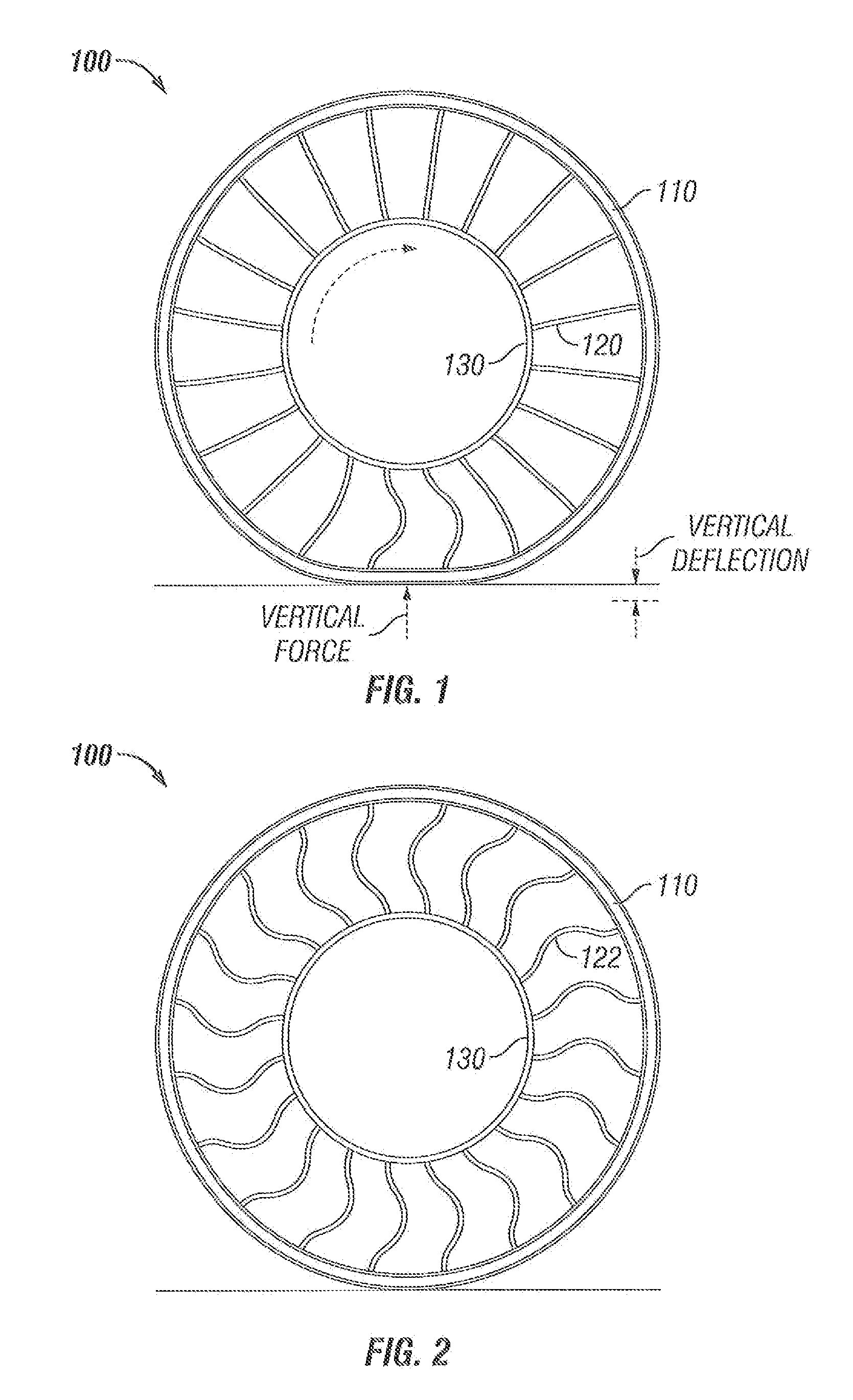
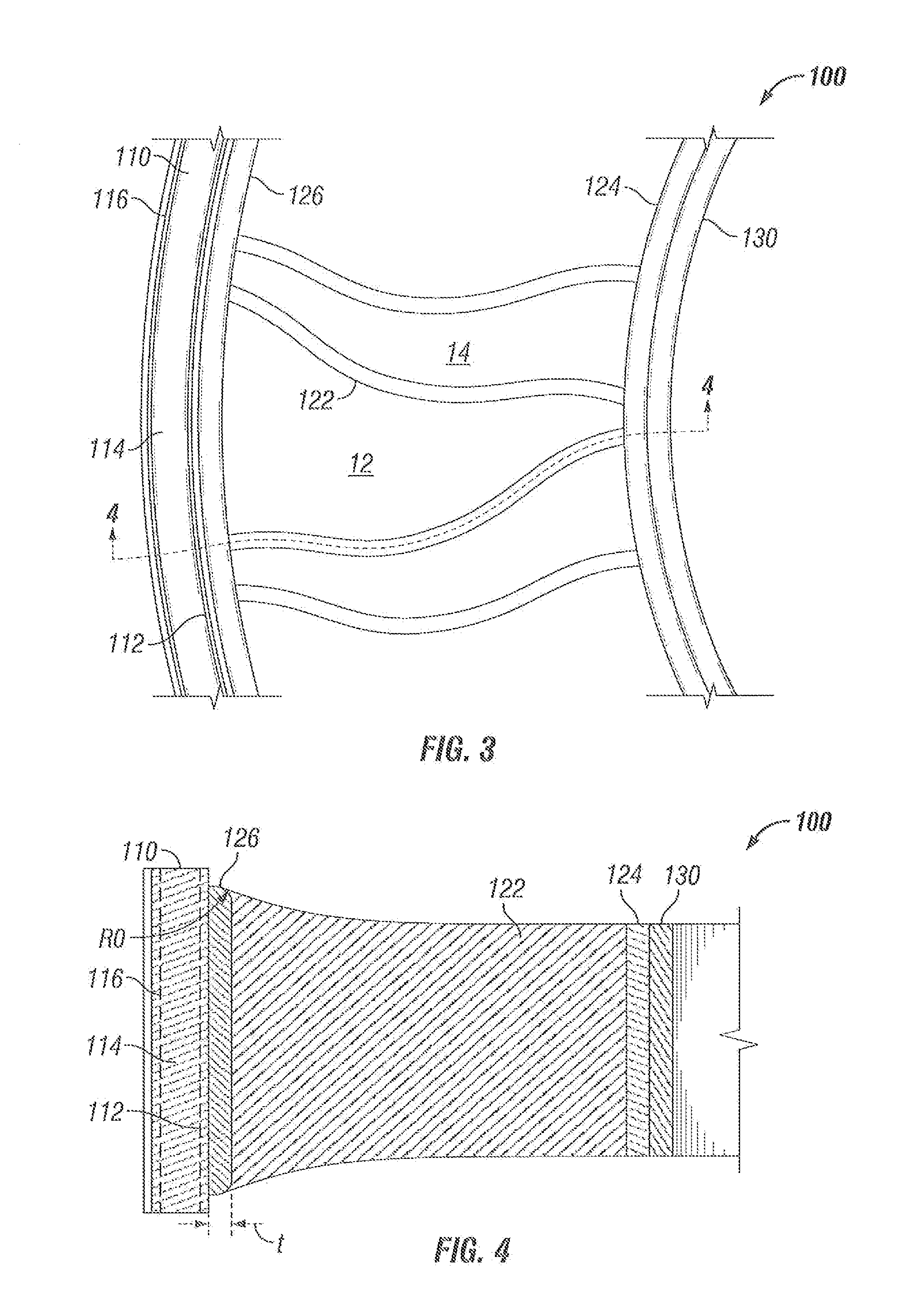
[0006]A molded article comprises an outer interface element having a circumference and an axial width, an inner interface element having a circumference and an axial width, and a plurality of web spokes positioned therebetween. The web spokes are oriented in a generally radial direction. The common surfaces of the inner interface element, the outer interface element, and a pair of adjacent web spokes forms a void space bounded by, the common surfaces. At least a portion of the interface element common to one of the void spaces has an edge radius having a variation from a maximum radius at a circumferential location corresponding to a mid point between a pair of adjacent web spokes to a minimum radius at the intersection of the interface element with the web spoke.

[0007]In an exemplary embodiment of the molded article, the variation off the edge radius is defined by a set of decreasing radii at circumferential locations between the midpoint between a pair of adjacent web spokes and a...


PUM

PropertyMeasurementUnit
Fractionaaaaaaaaaa
Fractionaaaaaaaaaa
Fractionaaaaaaaaaa

Abstract

A molded article comprises an outer interface element, an inner interface element, and a plurality of web spokes positioned therebetween. The common surfaces of the inner and outer interface elements and a pair of adjacent web spokes form a void space. The surface of at least a portion of an interface element common to one of the voids has an edge radius with a variation from a maximum radius at a circumferential location corresponding to a mid point between a pair of adjacent web spokes to a minimum radius at a circumferential location corresponding to the intersection of the interface element with the web spoke.

Description

BACKGROUND[0001]Non-pneumatic deformable structures for use in the support of loads under rolling conditions, such as to support loads for automotive vehicles have been described, for example in U.S. Pat. No. 7,201,194, which is commonly owned by the assignee of the current invention and is incorporated by reference in its entirety. The structurally supported, non-pneumatic tire disclosed therein includes an annular band that supports the load, a plurality of web spokes that transmit in tension the load forces between the annular band and a wheel or hub. A particularly useful design for the web spokes that improves spoke durability and allows the designer to vary the initial stiffness of vertical load versus vertical deflection is disclosed in United States Patent Publication No. 2009 / 0294000A1, which is also commonly owned by the assignee of the current invention and is incorporated by reference in its entirety. The non-pneumatic article supports its load solely through the structu...

Claims


Application Information

Patent Timeline
IPC IPC(8): B60C7/10B28B1/093
CPCB60C2007/146B60C7/10B60C7/146B60C7/107
Inventor CRON, STEVEN M.
Owner MICHELIN RECH & TECH SA
Why Eureka
Try Eureka