Enhanced Filter Support Basket

a technology of supporting basket and filter, which is applied in the direction of moving filter element filters, filtration separation, and separation processes, etc., can solve the problems of contaminated fluid bypassing the filter, difficult maintenance of the sealing relationship between the filter element and the filtration vessel, and large filtration vessels currently known in the art are costly to manufacture and maintain, so as to reduce the manufacturing cost of the filtration vessel , the effect of resiliency and flexibility

Active Publication Date: 2013-03-14
PARKER INTANGIBLES LLC
View PDF9 Cites 21 Cited by
  • Summary
  • Abstract
  • Description
  • Claims
  • Application Information

AI Technical Summary

Benefits of technology

[0009]Also preferably, the seal has an annular sealing flange and an annular base portion and may be a “chevron” type seal. The annular base portion is carried by a first end cap of the filter element, and the annular sealing flange has an annular terminating end. In one embodiment, the annular terminating end is spaced radially inside an inner peripheral surface of the first end cap. In an alternative embodiment, the annular terminating end is spaced radially outside an outer peripheral surface of the first end cap. The seal is elastomeric, and has sufficient resiliency and flexibility to conform and seal to a non-round

Problems solved by technology

Fluid streams such as liquid flows and gaseous flows (e.g. air flows) often carry particulates that are often undesirable contaminants entrained in the fluid stream.
Large filtration vessels currently known in the art are costly to manufacture and maintain due to the size of the components and their inaccessibility within the outer housing.
When components in the filtration vessel are imperfectly manufactured, a

Method used


Image

  • Enhanced Filter Support Basket
  • Enhanced Filter Support Basket
  • Enhanced Filter Support Basket

Examples


Embodiment Construction

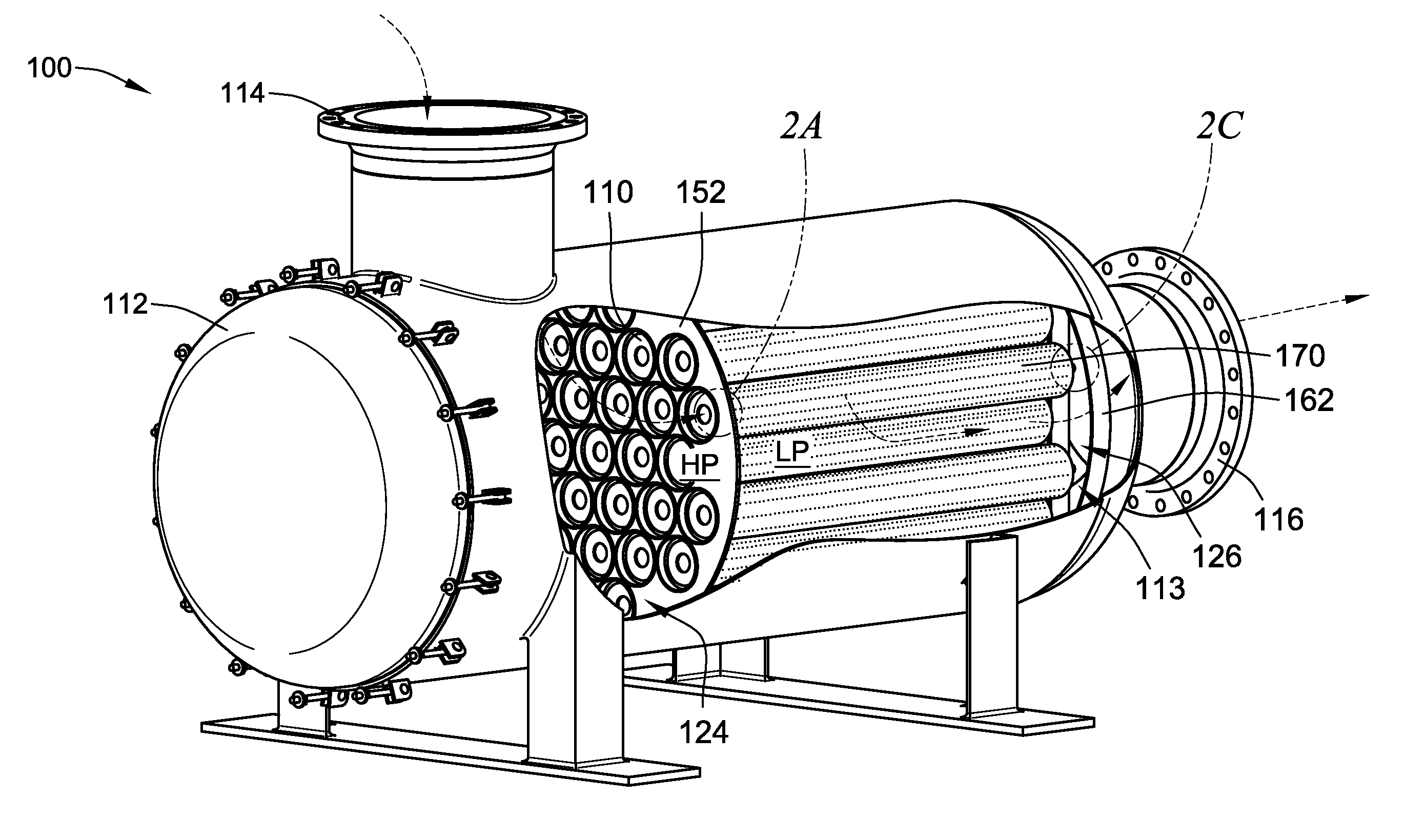
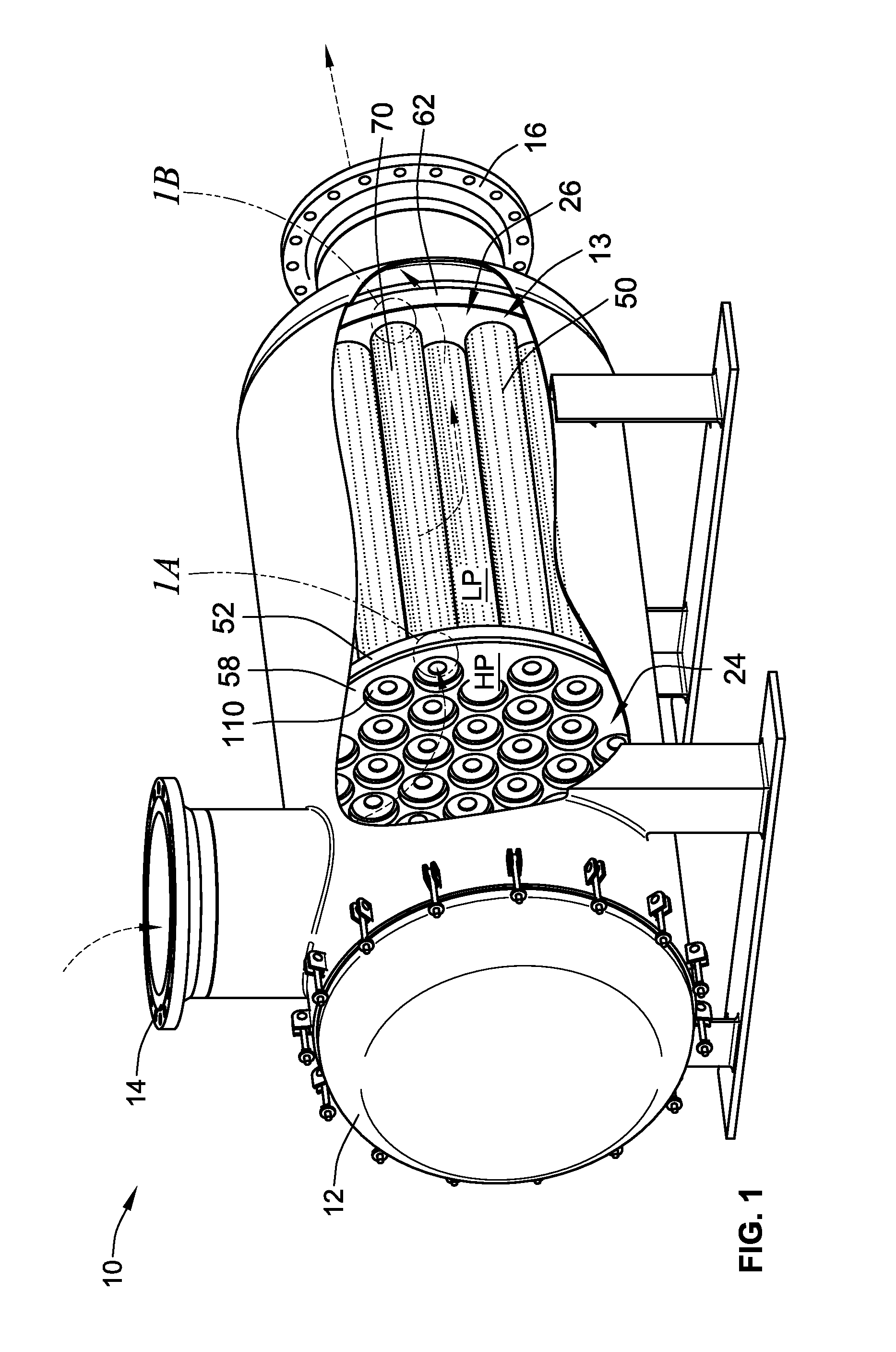
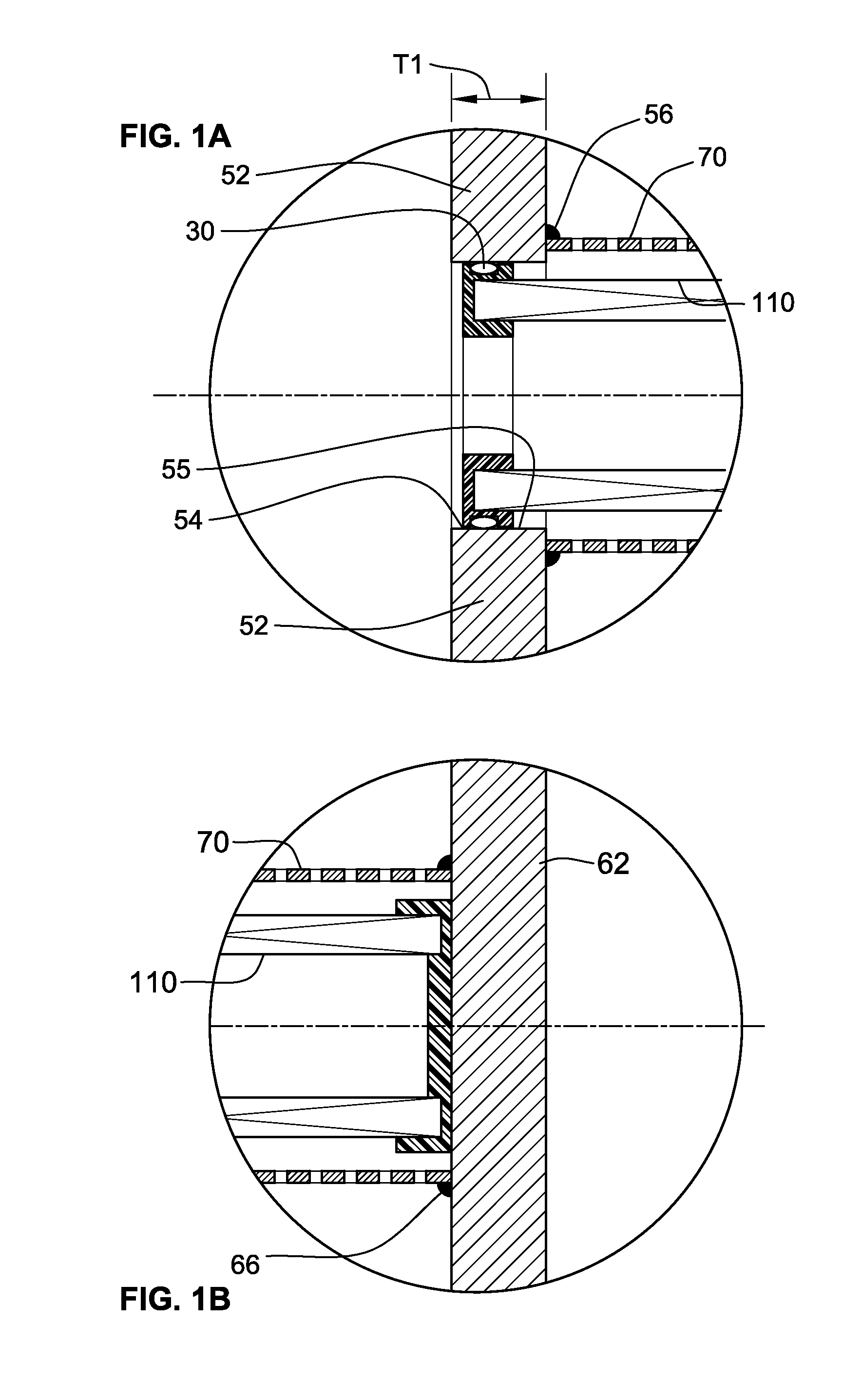
[0036]FIGS. 1, 1A, and 1B depict a filtration vessel 10 known in the prior art. The filtration vessel 10 has an outer housing 12 with an inlet port 14 and an outlet port 16, and defines a filtration chamber 13. A filter support structure 50 is disposed within the outer housing 12. The filter support structure 50 has a partition plate 52, which divides the filtration chamber 13 into an inlet compartment 24 and an outlet compartment 26. The partition plate 52 has a plurality of flow openings 54. From each flow opening 54, a first end of a corresponding perforated sleeve 70 extends into the outlet compartment 26 and terminates at a second end, attached to a back support plate 62. Each perforated sleeve 70 is adapted to receive a filter element 110.

[0037]The partition plate 52 defines a plurality of radial sealing surfaces 55 along an inner periphery of each flow opening 54. As such, a seal such as an o-ring 30 retained by a first end cap of each filter element 110 attempts to seal the ...


PUM

PropertyMeasurementUnit
Lengthaaaaaaaaaa
Lengthaaaaaaaaaa
Lengthaaaaaaaaaa

Abstract

A filtration vessel is provided with improved sealing surfaces and alignment methods. The sealing surface is provided by a perforated sleeve within the filtration vessel. An alignment mechanism is provided which allows for improved servicing of the filtration vessel.

Description

FIELD OF THE INVENTION[0001]This invention generally relates to filter systems, and in particular to filtration vessels, and methods for servicing the same.BACKGROUND OF THE INVENTION[0002]Fluid streams such as liquid flows and gaseous flows (e.g. air flows) often carry particulates that are often undesirable contaminants entrained in the fluid stream. Filters are commonly employed to remove some or all of the particulates from the fluid stream. Filtration vessels having one or more filters, often arranged in parallel circuit provide a known way to filter a high volume of fluid. Typically, a filtration vessel includes a filter support structure disposed within an outer housing, which may be adapted to provide radial and axial support to filter elements during operation.[0003]Large filtration vessels currently known in the art are costly to manufacture and maintain due to the size of the components and their inaccessibility within the outer housing. When components in the filtration ...

Claims


Application Information

Patent Timeline
IPC IPC(8): B01D35/02B23P6/00
CPCB01D29/52B01D29/96Y10T29/49718B01D2201/291B01D2201/34B01D2201/043B01D2201/0453
Inventor BURNS, DAVID J.CLOUD, DANIEL M.BOSWELL, TYLER GLENNJONES, ARTIMUS CHARLES
Owner PARKER INTANGIBLES LLC
Why Eureka
Try Eureka