Fiber orienting technology for a grinding machine

a technology of fiber orienting and grinding machine, which is applied in the direction of solid separation, sorting, kitchen equipment, etc., can solve the problems of affecting the quality of the product, the turbulence of the meat flow, and the dead spots of the product, so as to reduce the release and mixing of myosin, improve the bite/binding effect, and reduce the activity of myosin

Active Publication Date: 2013-03-14
FORMTEC
View PDF13 Cites 14 Cited by
  • Summary
  • Abstract
  • Description
  • Claims
  • Application Information

AI Technical Summary

Benefits of technology

[0013]It is an object of the present invention for the fiber orientation technology to reduce the release and mixing of myosin with actin. It is an object of the present invention for the fiber orientation technology to control orientation of the fiber. It is an object of the present invention for the fiber orientation technology to provide less myosin activity resulting in a better bite / bind and control over the final cook shape.

Problems solved by technology

Current forming technology relies on high pressure, speed and complicated material flow pathways which produce a product lacking in quality.
Fill hole shape and spacing can cause dead spots and turbulence in the meat flow.

Method used


Image

  • Fiber orienting technology for a grinding machine
  • Fiber orienting technology for a grinding machine
  • Fiber orienting technology for a grinding machine

Examples


Embodiment Construction

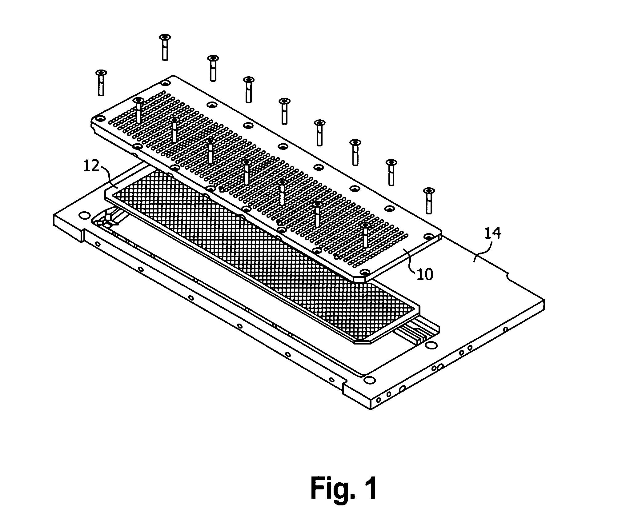
[0058]FIG. 1 shows an unassembled view of a fill plate 10, stripper plate 12 and a top plate 14.

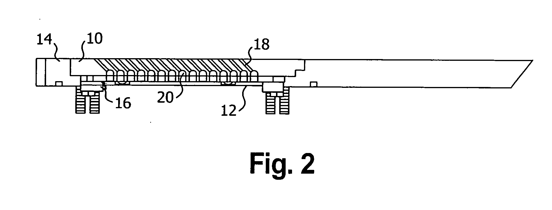
[0059]FIG. 2 shows an assembled view of the fill plate 10, stripper plate 12 and top plate 14, further comprising a stripper plate spacer and hold down 16, a cylindrical section 18 and a curved section 20.

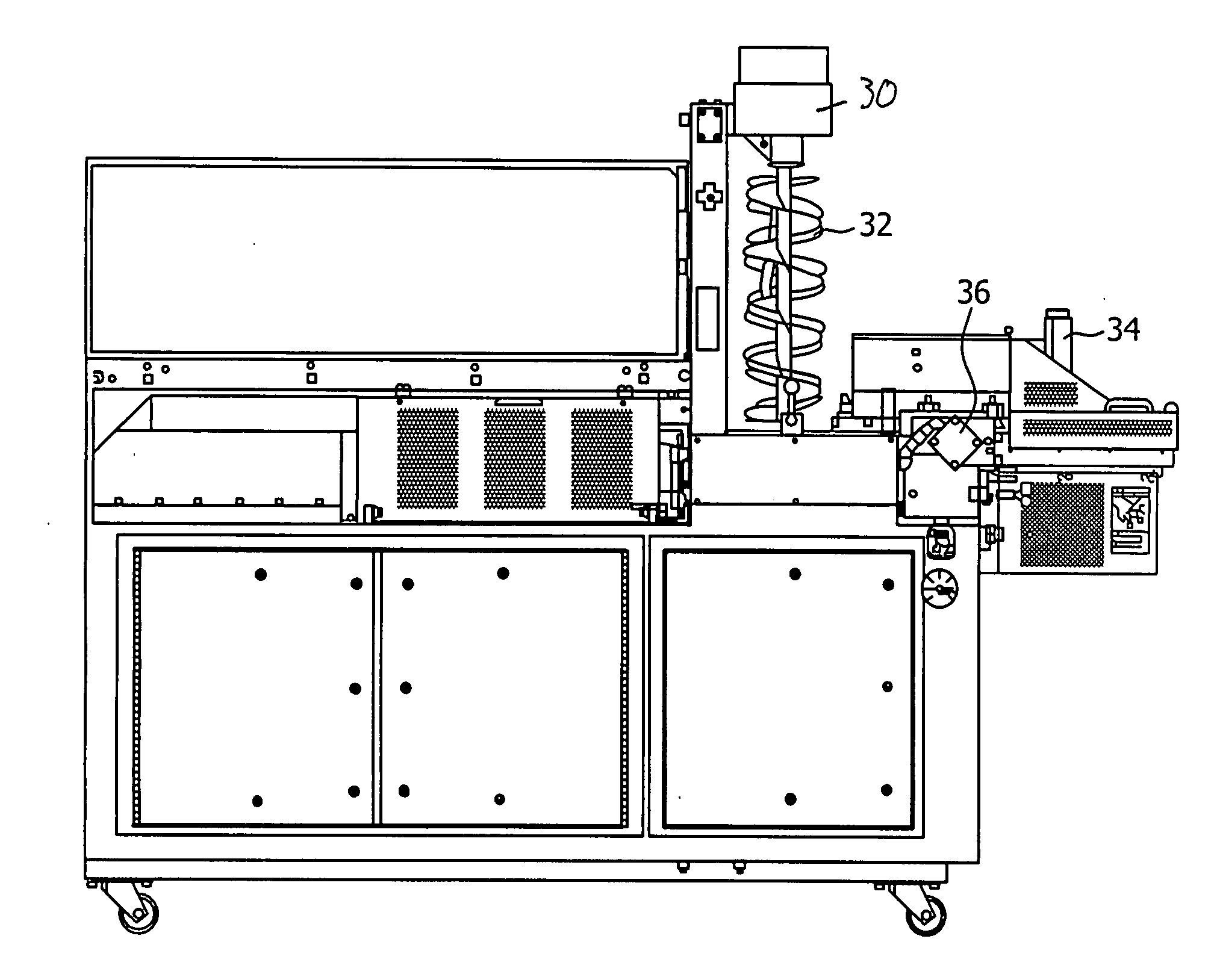
[0060]FIG. 3 shows a side view of the patty molding machine having an auger driver motor 30 an auger 32, knockouts 34 and a shear plate drive cylinder 36.

[0061]FIG. 4 shows a top view of an embodiment of the present invention, having a stripper plate drive 40, a fill and stripper plate assembly 42, a mold plate 44 and a draw bar 46.

[0062]FIG. 5 shows a breather plate 60 having orifices 62 and 64 in the breather plate 60.

[0063]FIG. 6 shows the breather plate 70 having orifices 72 and 74. The channels are made up of a spherical section 76 intersecting a cylindrical section 78.

[0064]FIG. 7 further shows the orifice 74 having the spherical section 76 and a cylindrical section 78.

[0065]FIG. 8...


PUM


Abstract

An apparatus and method for accelerating food product in order to cause the product to be stretched aligning the fibers of the product.

Description

RELATED APPLICATIONS[0001]The present application is a continuation-in-part of pending application Ser. No. 13 / 199,910 filed on Sep. 12, 2011.FIELD OF THE INVENTION[0002]The present invention relates to an apparatus and method for accelerating food product in order to cause the product to be stretched aligning the fibers of the product.BACKGROUND OF THE INVENTION[0003]Current forming technology relies on high pressure, speed and complicated material flow pathways which produce a product lacking in quality. High pressure works the meat cells, the higher the pressure the more massaging or squeezing of the meat cells takes place. High speed combined with a complicated flow path massages and works the meat product, releasing myosin / actin from the cells causing the muscle fiber to bind together and contract (protein bind). The contraction takes place during high heat application as in cooking. The action of the meat fiber is to contract in length, this contraction combined with protein b...

Claims


Application Information

Patent Timeline
Patent Type & Authority Applications(United States)
IPC IPC(8): A47J43/07B02C18/30B02C23/02B07C5/12
CPCA47J43/07B02C2018/308B02C18/365B02C18/30
Inventor WOLFF, JAMES B.
Owner FORMTEC
Why Eureka
Try Eureka