Antenna Integrated into Optical Element

an optical element and antenna technology, applied in the field of radio frequency antennas, can solve the problems of cost, the need for a separate antenna structure, and the inability to achieve the optimal radio frequency performance of the antenna

Inactive Publication Date: 2013-03-14
GREENWAVE SYST
View PDF2 Cites 60 Cited by
  • Summary
  • Abstract
  • Description
  • Claims
  • Application Information

AI Technical Summary

Problems solved by technology

This may create less than optimum radio frequency performance for the antenna.
Other embodiments may include a separate ante

Method used


Image

  • Antenna Integrated into Optical Element
  • Antenna Integrated into Optical Element
  • Antenna Integrated into Optical Element

Examples


Embodiment Construction

[0015]In the following detailed description, numerous specific details are set forth by way of examples in order to provide a thorough understanding of the relevant teachings. However, it should be apparent to those skilled in the art that the present teachings may be practiced without such details. In other instances, well known methods, procedures and components have been described at a relatively high-level, without detail, in order to avoid unnecessarily obscuring aspects of the present concepts. A number of descriptive terms and phrases are used in describing the various embodiments of this disclosure. These descriptive terms and phrases are used to convey a generally agreed upon meaning to those skilled in the art unless a different definition is given in this specification. Some descriptive terms and phrases are presented in the following paragraphs for clarity.

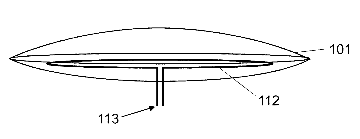
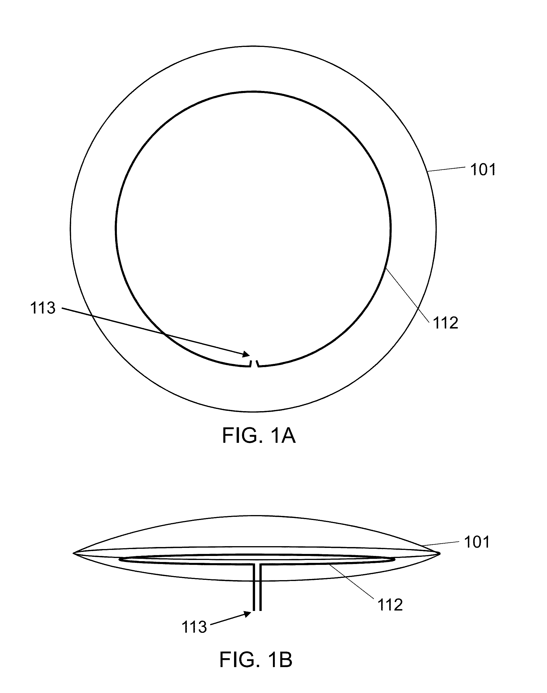
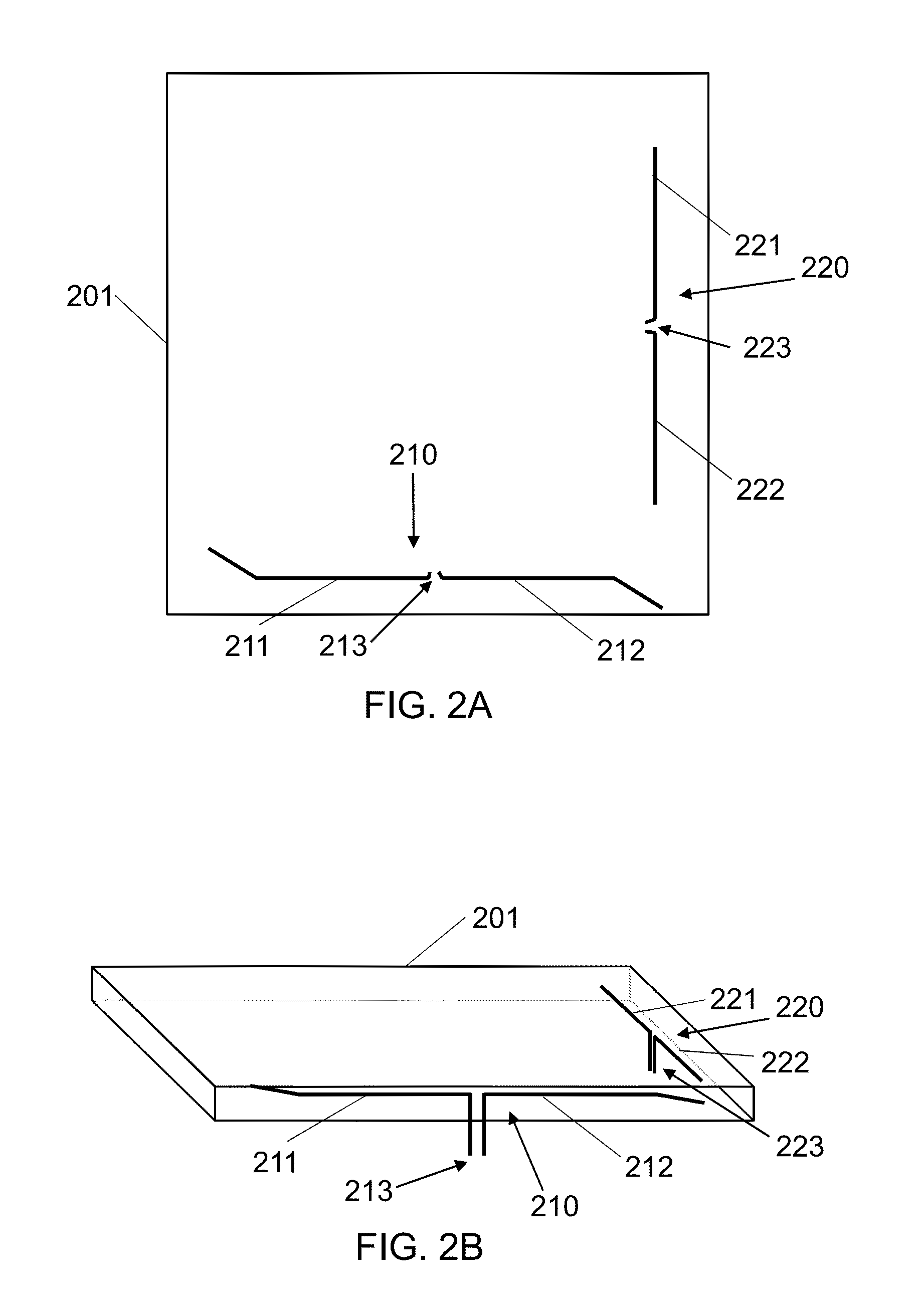
[0016]An optical element is a component part that is transparent or translucent, allowing at least some light to pas...


PUM


Abstract

An antenna is integrated with an optical element, such as a lens, a collimator, a diffuser, a reflector, or some other part that allows at least some light to pass through or reflects light. In some embodiments, the antenna is molded into the optical element. In other embodiments, the antenna is printed on, or attached to, the surface of the optical element. The antenna may be formed from a transparent or a non-transparent conductor, depending on the embodiment.

Description

BACKGROUND[0001]1. Technical Field[0002]The present subject matter relates to radio frequency antennas. More specifically it relates to integrating an antenna into an optical element.[0003]2. Description of Related Art[0004]As home automation becomes more important, it is becoming more and more common to include radio frequency communication into a lighting apparatus. In many current embodiments, an antenna is integrated with a radio frequency module. The placement of the radio frequency module within the lighting apparatus may be dictated by factors other than radio frequency performance, such as the form factor of the lighting apparatus or thermal issues. This may create less than optimum radio frequency performance for the antenna.[0005]Other embodiments may include a separate antenna, but this creates a different set of problems including cost and the need for structure to support the separate antenna.SUMMARY[0006]A lighting apparatus includes a light source, an optical element ...

Claims


Application Information

Patent Timeline
IPC IPC(8): H01Q1/44
CPCH01Q1/44F21K9/233F21Y2115/10
Inventor JONSSON, KARLMANNICHE, MARTIN
Owner GREENWAVE SYST
Why Eureka
Try Eureka