Lifting frame device

a technology of lifting frame and frame body, which is applied in the direction of passenger handling apparatus, waterborne vessels, cargo handling apparatus, etc., can solve the problems that the conventional a-frame cannot, however, increase the lifting radius and/or the lifting height, and achieve the effect of less torque critical, increased lifting radius and lifting heigh

Inactive Publication Date: 2013-03-21
ROLLS ROYCE MARINE
View PDF8 Cites 7 Cited by
  • Summary
  • Abstract
  • Description
  • Claims
  • Application Information

AI Technical Summary

Benefits of technology

[0019]By means of the present invention there is provided a lifting device that is less torque critical than conventional lifting devices. When the lifting device is loaded, the vertical booms will take up compressive forces, whilst the tension rods will take up tensile forces. As a result, fewer cylinders can be used for movement of the lifting device. In addition, a lifting device is provided having increased lifting radius and lifting height compared with conventional lifting devices.

Problems solved by technology

A conventional A-frame of this kind cannot, however, increase its lifting radius and / or lifting height.

Method used


Image

  • Lifting frame device
  • Lifting frame device

Examples


Embodiment Construction

[0026]For convenience and clarity in describing these embodiments, similar elements or components appearing in different figures will have the same reference numbers.

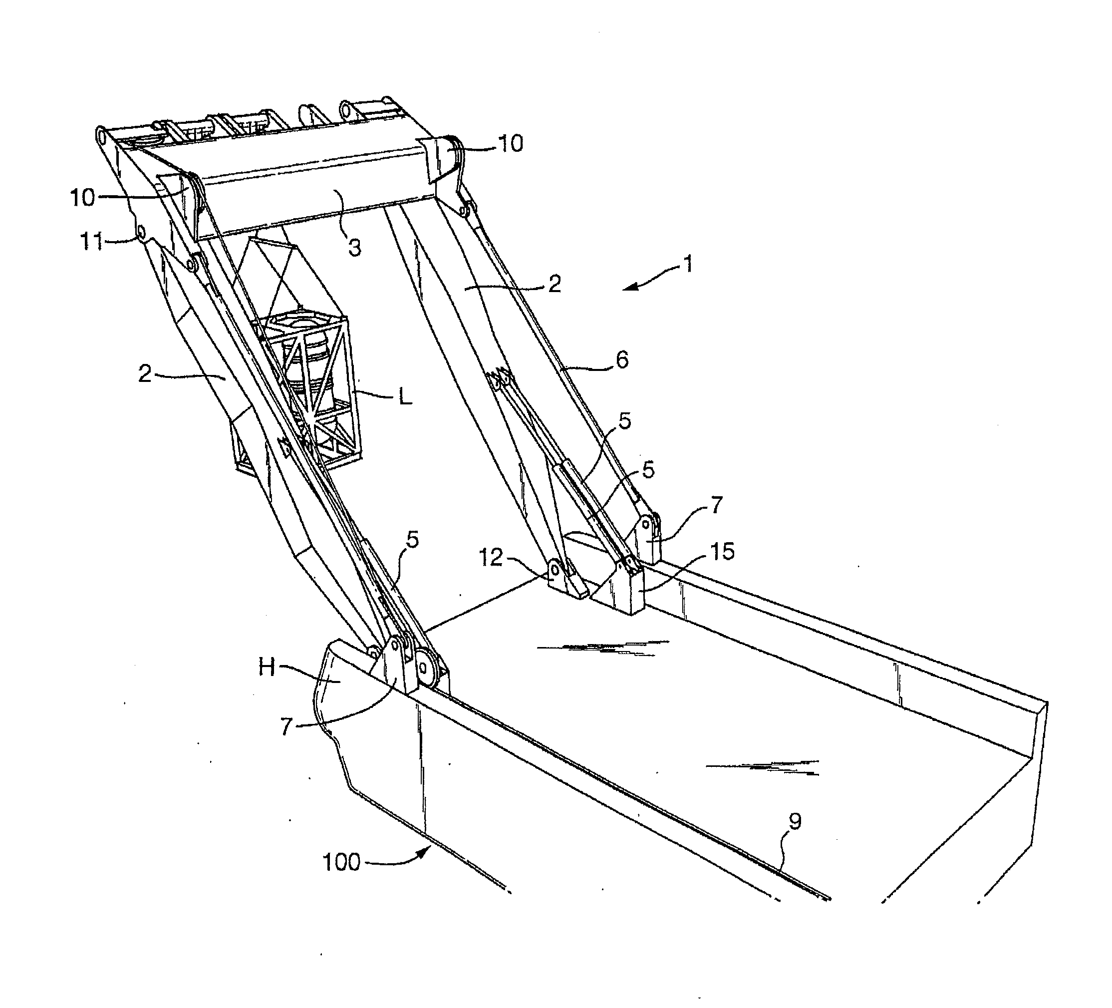
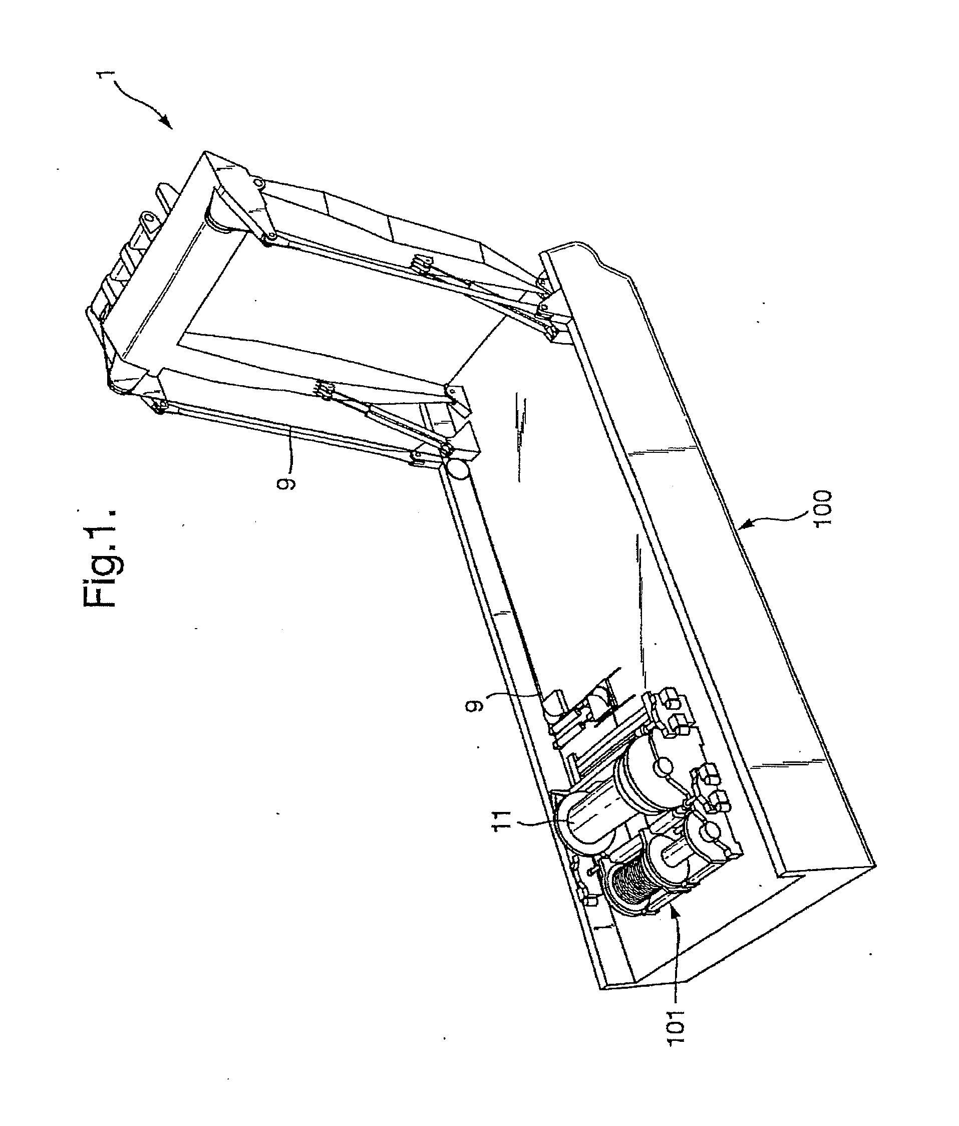
[0027]FIG. 1 shows a lifting device 1 according to the present invention, wherein the lifting device 1 is arranged on the deck of a vessel 100. The lifting device 1 is arranged at a rear end of the vessel 100. A winch arrangement 101, comprising a winch 11, is connected via at least one lifting wire 9 to the lifting device 1 hook block 8 (see also FIG. 2), such that a load L can be lifted up or down.

[0028]The winch arrangement 101 comprises a plurality of drums and winches 11, guiding and tensioning means (not shown) for the lifting wire 9, braking means (not shown) etc. Since the winch arrangement 101 is a conventional arrangement, it will not be described in more detail here.

[0029]The lifting device 1 according to the present invention is shown in greater detail in FIG. 2, in a side view and a front view (i.e., in the...


PUM


Abstract

A lifting device for handling and/or moving loads, including two vertical booms which via one of their ends are pivotally connected to a base and via their opposite ends are pivotally connected to a horizontal beam, forming a frame for the lifting device wherein at least one cylinder is connected to at least one of the vertical booms so as to be able to turn the lifting device around the pivot point. The horizontal beam is further pivotally connected to at least one tension rod. The vertical booms, the tension rods and the horizontal beam will then be pivotal in relation to each other. By means of the present invention, a less torque-critical lifting device is provided, as the vertical booms, when handling and/or moving a load, will take up compressive forces, while the tension rods will take up tensile forces.

Description

[0001]Related cases: This case claims priority under 35 U.S.C. §119, 120 and / or 365 on Norway Patent Appln. No. 2010 0478 filed 31 Mar. 2010 and PCT / NO2011 / 000114 filed 31 Mar. 2011.FIELD OF THE INVENTION[0002]The present invention relates to a lifting device for handling and / or moving loads, and more particularly the present invention relates to a lifting frame comprising at least one tension rod.BACKGROUND AND PRIOR ART[0003]When moving or transferring loads offshore, where the moving or transfer may take place between two vessels, between a vessel and an offshore structure, or through the deployment / boarding of loads into / from the sea, a lifting device known as an A-frame is used. The A-frame is constituted of two side booms and a top boom, which side booms are connected to one or more cylinders. Furthermore, the A-frame is pivotally connected to an underlying surface. By controlling the stroke of the cylinders, the A-frame can be made to rotate about the pivotal connection. A li...

Claims


Application Information

Patent Timeline
Patent Type & Authority Applications(United States)
IPC IPC(8): B66C23/06
CPCB66C23/52B66C23/06B63B27/19
Inventor SALTHAMMER, JOERNMYKLEBUST, YNGVE BOE
Owner ROLLS ROYCE MARINE
Why Eureka
Try Eureka