Winding for an ac machine

a technology of alternating current and winding, which is applied in the direction of windings, dynamo-electric components, and magnetic circuit shapes/forms/constructions, etc., can solve the problems of wasting a large amount of the capacity of the alternating current machin

Inactive Publication Date: 2013-03-28
ABB TECH AG
View PDF2 Cites 17 Cited by
  • Summary
  • Abstract
  • Description
  • Claims
  • Application Information

AI Technical Summary

Problems solved by technology

Such an arrangement can, however, waste much of the capacity of the alternating current machine.

Method used


Image

  • Winding for an ac machine
  • Winding for an ac machine
  • Winding for an ac machine

Examples


Embodiment Construction

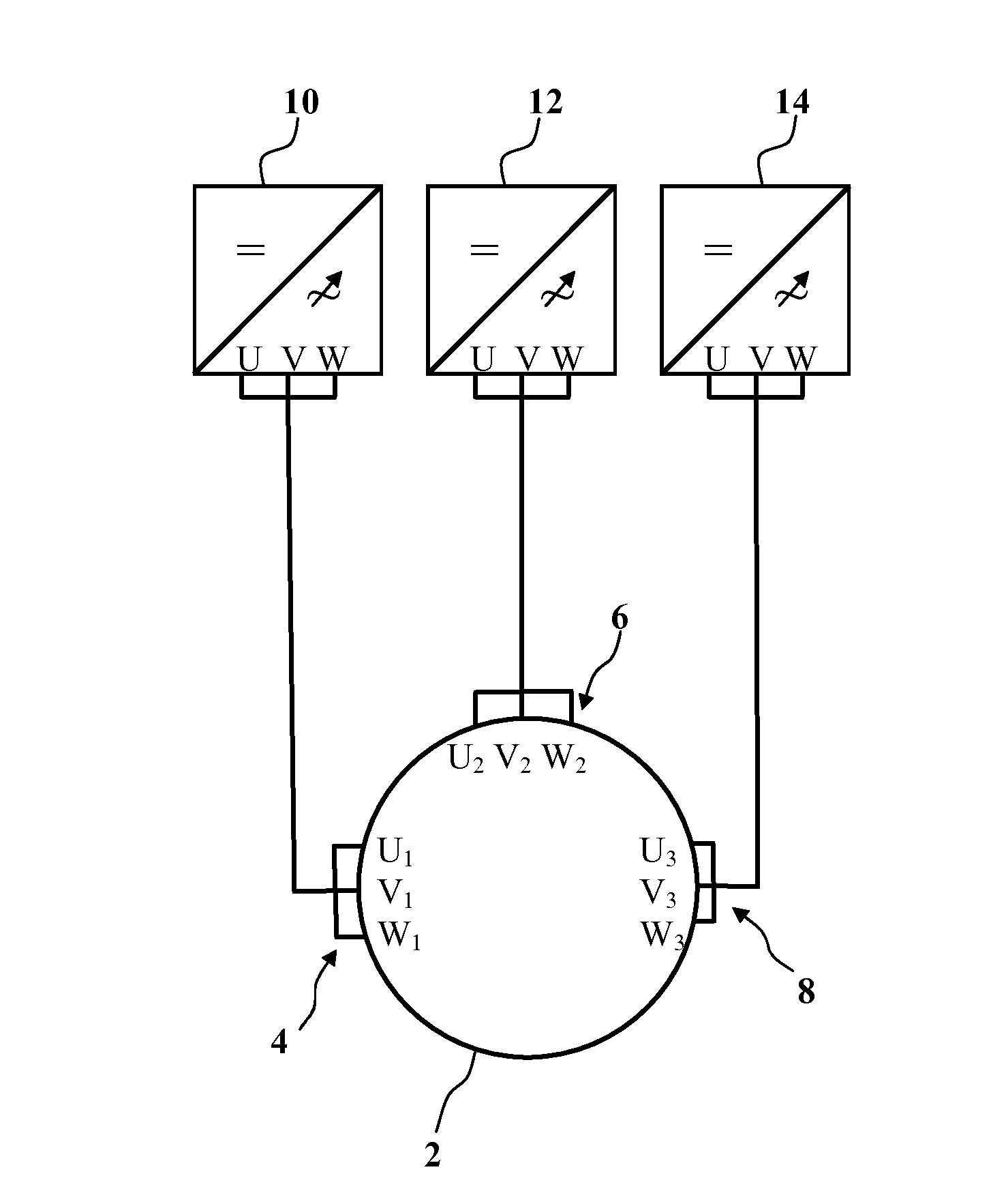
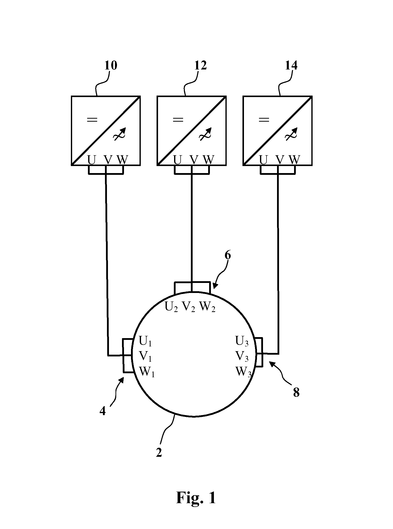
[0017]An alternating current machine according to an exemplary embodiment of the disclosure can include redundant stator windings, which utilize the properties and capacity of the alternating current machine and the control equipment controlling it more efficiently than before. In order to achieve this, exemplary embodiments of the disclosure include a number of parallel winding groups being higher than two, and by the number of poles of the alternating current machine being an even number, and a multiple of the number of winding groups.

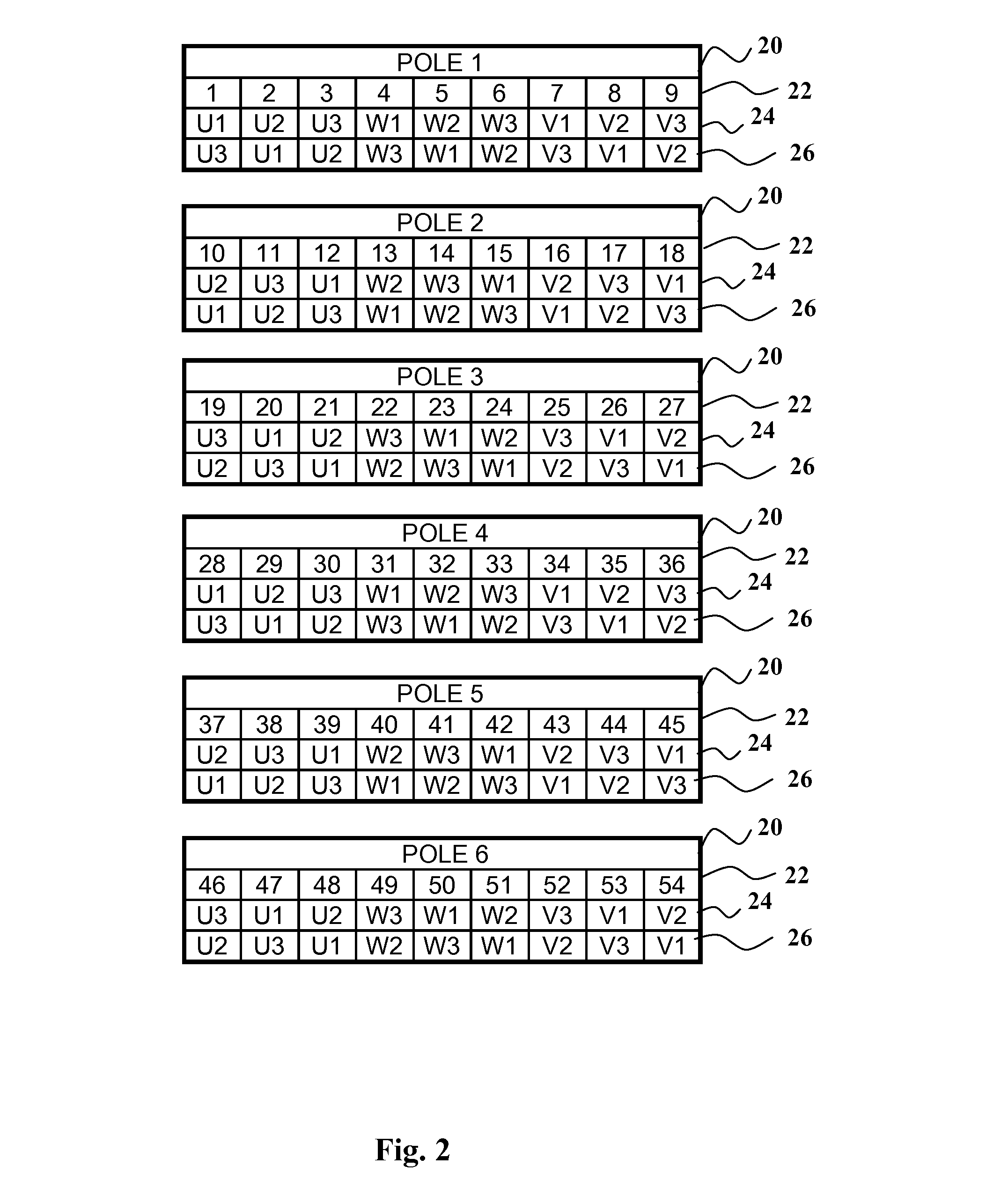
[0018]In an exemplary embodiment of the disclosure, the location of coils belonging to different groups regularly cycles in the area of the poles, and these coils are connected in series. When the number of slots per phase, per pole (i.e. in Finnish “Vakolukv”) is the same as the number of individual windings or its multiple, the branches belonging to different windings can be made identical electrically. The benefit of the rotating location of coils...


PUM


Abstract

A stator winding is disclosed for a multiple-phase alternating current machine with several parallel winding groups (U1, V1, W1; U2, V2, W2; U3, V3, W3), each of which can be supplied with separate power sources. Locations of the winding groups can be cyclically shifted when moving from one pole to another. The number of parallel winding groups (U1, V1, W1; U2, V2 ,W2 ;U3 ,V3 , W3) can be higher than two, and the number of poles of the alternating current machine can be an even figure that is a multiple of the number of winding groups.

Description

RELATED APPLICATION[0001]This application claims priority as a continuation application under 35 U.S.C. §120 to PCT / FI2011 / 050479, which was filed as an International Application on May 25, 2011 designating the U.S., and which claims priority to Finnish Application 20105588 filed in Finland on May 25, 2010. The entire contents of these applications are hereby incorporated by reference in their entireties.FIELD[0002]The disclosure relates to the winding of a multi-phase alternating current winding, for example, a stator winding with several parallel winding groups, each of which can be supplied with separate power sources, wherein the alternating current machine has several poles, and wherein the location of the winding groups is shifted cyclically when moving from one pole to another.BACKGROUND INFORMATION[0003]Several winding systems are used in certain implementations of alternating current machines, making it possible to implement and group the windings in an appropriate manner, ...

Claims


Application Information

Patent Timeline
Patent Type & Authority Applications(United States)
IPC IPC(8): H02K3/28
CPCH02K3/28H02K1/06H02K16/04
Inventor JARVINEN, JUKKAKANERVA, SAMI
Owner ABB TECH AG
Why Eureka
Try Eureka