Wave powered buoyancy control system for floating wave power plants

a technology of buoyancy control system and wave power plant, which is applied in the field of wave energy research, can solve the problems of unprofitability and destruction of wave energy converters

Inactive Publication Date: 2013-04-04
STRAUMEKRAFT
View PDF12 Cites 5 Cited by
  • Summary
  • Abstract
  • Description
  • Claims
  • Application Information

AI Technical Summary

Benefits of technology

[0010]In general, in one aspect, one or more embodiments of the invention include a ballast chamber with a seawater inlet/outlet that prevents compressible fluid from...

Problems solved by technology

If not, the wave energy converter will be destroyed by the waves unless,...

Method used


Image

  • Wave powered buoyancy control system for floating wave power plants
  • Wave powered buoyancy control system for floating wave power plants
  • Wave powered buoyancy control system for floating wave power plants

Examples


Embodiment Construction

[0069]In embodiments of the invention, numerous specific details are set forth in order to provide a more thorough understanding of the invention. However, it will be apparent to one with ordinary skill in the art that the invention may be practiced without these specific details. In other instances, well-known features have not been described in detail to avoid obscuring the invention.

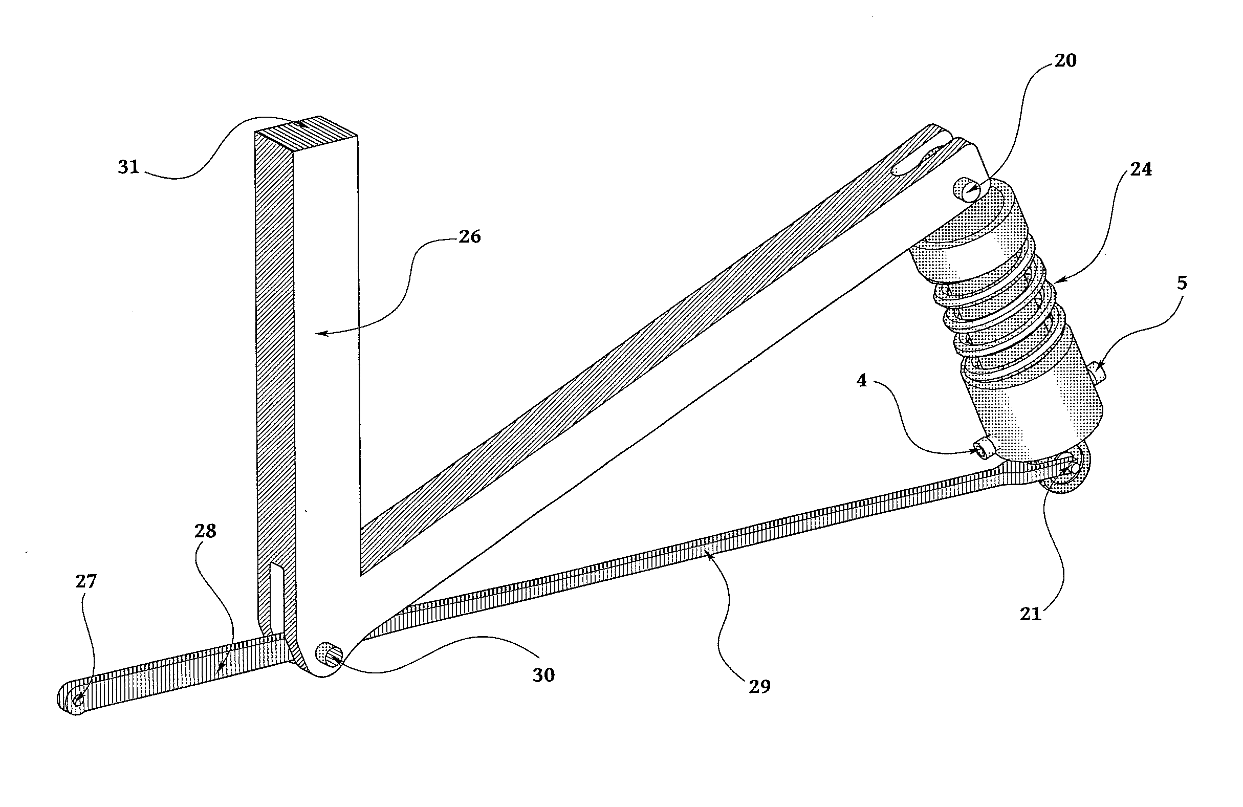
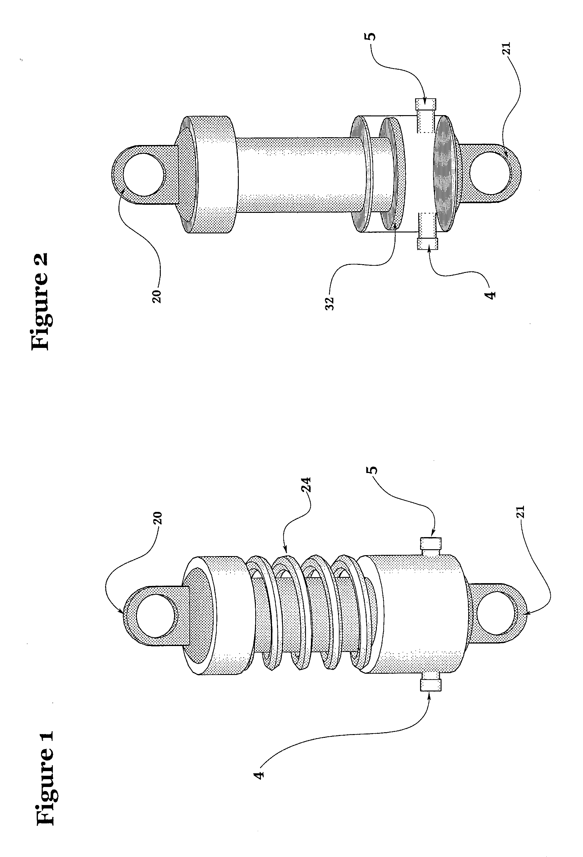
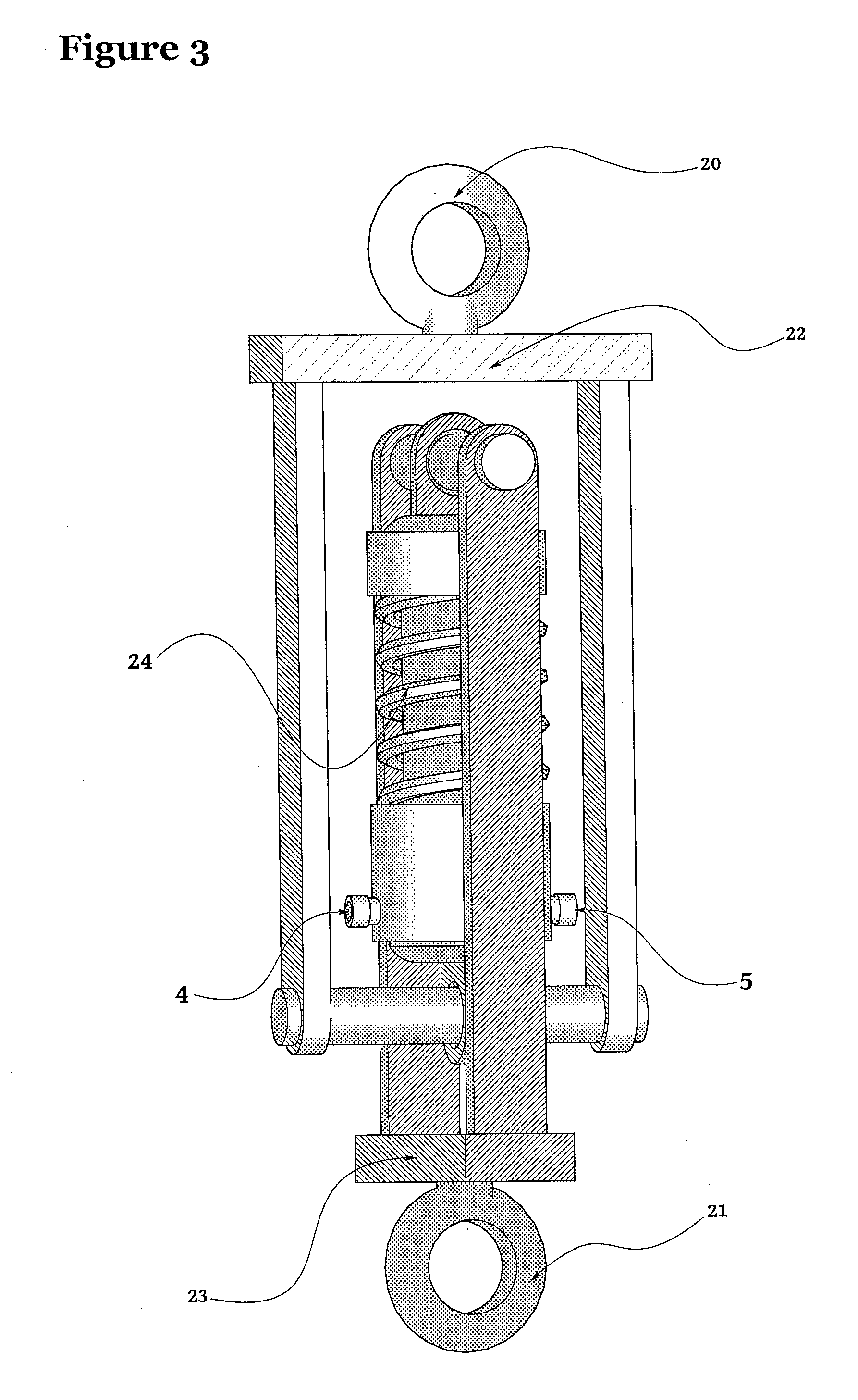
[0070]FIGS. 4, 5, 8, and 9 show a compressor pump 1 that is connected to a buoy, or a floating section 2, of a wave energy converter in accordance with one or more embodiments of the invention. The location of the compressor pump's connection may vary, depending on which kind of wave energy converter it is installed as a part of. A suitable location may be at a point in the structure where the flow of energy is high, or at a point where the mechanical forces which act from the waves upon the buoy, or the floating section, in extreme weather are particularly strong. For a wire anchored point absorber, ...


PUM


Abstract

A system for controlling the submersion of a floating section/body of a wave power plant includes a pump connected to a compressible fluid accumulator and a ballast chamber. The pump is arranged to pump compressible fluid from the ballast chamber to the accumulator. The system further includes an opening in a wall of the ballast chamber that enables the ballast chamber to let in seawater. Furthermore, the pump is powered by wave energy.

Description

CROSS-REFERENCE TO RELATED APPLICATION(S)[0001]This application is a national stage application of PCT / EP2010 / 067822, filed on Nov. 19, 2010, entitled “Wave Powered Buoyancy Control System for Floating Wave Power Plants,” which claims priority to United Kingdom Patent Application No. 0921079.0, filed on Dec. 1, 2009. Both PCT / EP2010 / 067822 and United Kingdom Patent Application No. 0921079.0 are incorporated by reference herein in their entireties.BACKGROUND OF THE INVENTION[0002]Experiences from the past decades and recent years of wave energy research have taught engineers that overload protection is an indispensable feature of any wave energy concept, if it is to have a chance of becoming commercially applicable.[0003]The amount of energy contained in the most extreme waves is so immense that a wave energy converter must have some strategy to avoid a too high degree of interaction with those vast concentrations of energy. If not, the wave energy converter will be destroyed by the ...

Claims


Application Information

Patent Timeline
IPC IPC(8): F03B13/14
CPCB63B22/20F03B13/14Y02E10/38F03B13/20Y02E10/30F03B13/187
Inventor STRAUME, INGVALDVISTE, ARILD
Owner STRAUMEKRAFT
Why Eureka
Try Eureka