Oscillating Piston-Type Wave Power Generation Method and System

a technology of oscillating pistons and wave power generation, which is applied in the direction of renewable energy generation, vessel construction, greenhouse gas reduction, etc., can solve the problems of high cost, inability to effectively utilize the energy of ocean waves, and inexhaustible renewable energy resources, so as to achieve effective utilization of wave height, strong wind resistance, and high utilization of wave height

Inactive Publication Date: 2015-09-24
QU YANMING
View PDF7 Cites 21 Cited by
  • Summary
  • Abstract
  • Description
  • Claims
  • Application Information

AI Technical Summary

Benefits of technology

[0061]1) Strong resistance to wind and waves
[0062]With the rope-control device, the stroke of the floating body will be no longer limited to the length of the hydraulic cylinder, thus enabling it to do work under greater waves.
[0063]2) High utilization of wave height
[0064]In the process of one rising wave, the hydraulic cylinder can do work for multiple times to effectively utilize the wave height.
[0066]As the rope releasing of the drum requires quite small force, the friction acting on the rope is greatly reduced, the service life of the rope is thus extended.

Problems solved by technology

Ocean wave energy is an inexhaustible and renewable energy resource.
Because the ocean is affected by the complex and varying natural factors, the changing size and form of the tide and the waves make it a great difficulty for people to use the energy of the ocean wave to generate stably.
Currently the mainly problems of various wave power generation systems are as follows: high cost, poor survivability, poor ability to adapt to different waves, poor corrosion resistance, low utilization rate of the wave height, low conversion efficiency, unstable output power, high failure rate, high maintenance costs and so on.
Therefore, the power moment cannot be formed, the output is almost zero, and the economic benefit is limited.
If the hydraulic cylinder is done quite long, it is a severe waste and a high cost, and a short one is not long enough to make a good use of a big wave.

Method used


Image

  • Oscillating Piston-Type Wave Power Generation Method and System
  • Oscillating Piston-Type Wave Power Generation Method and System
  • Oscillating Piston-Type Wave Power Generation Method and System

Examples


Embodiment Construction

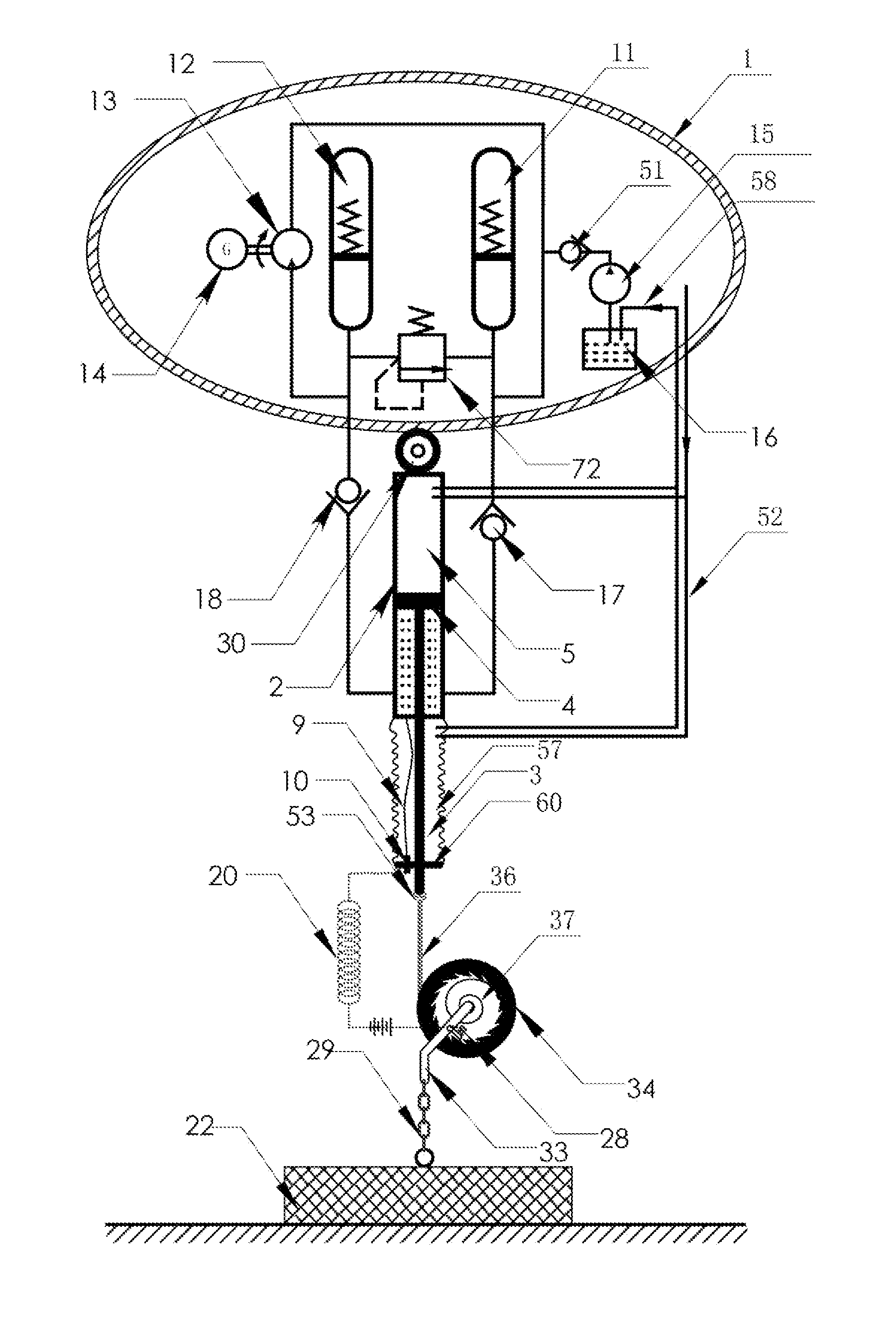
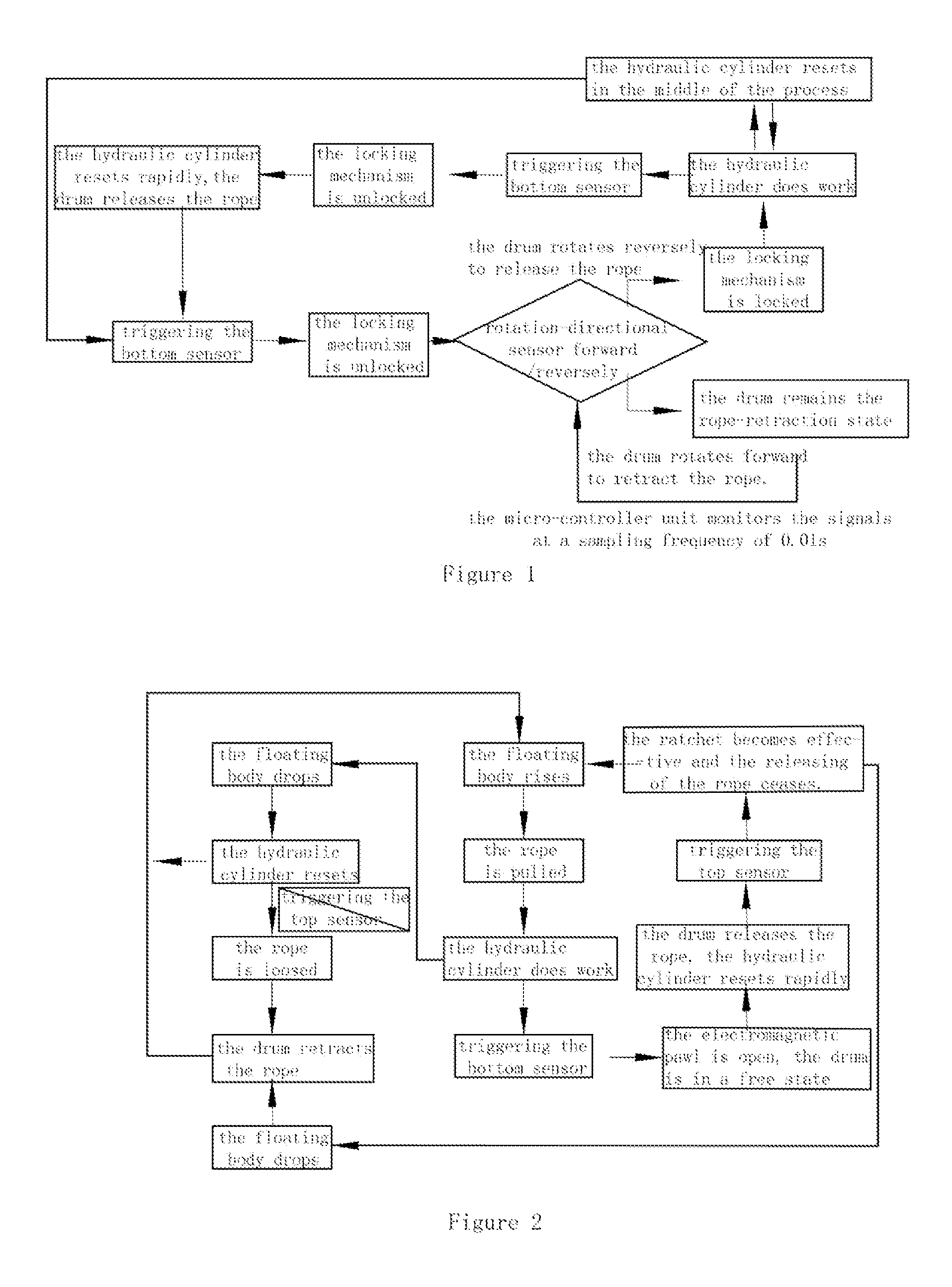
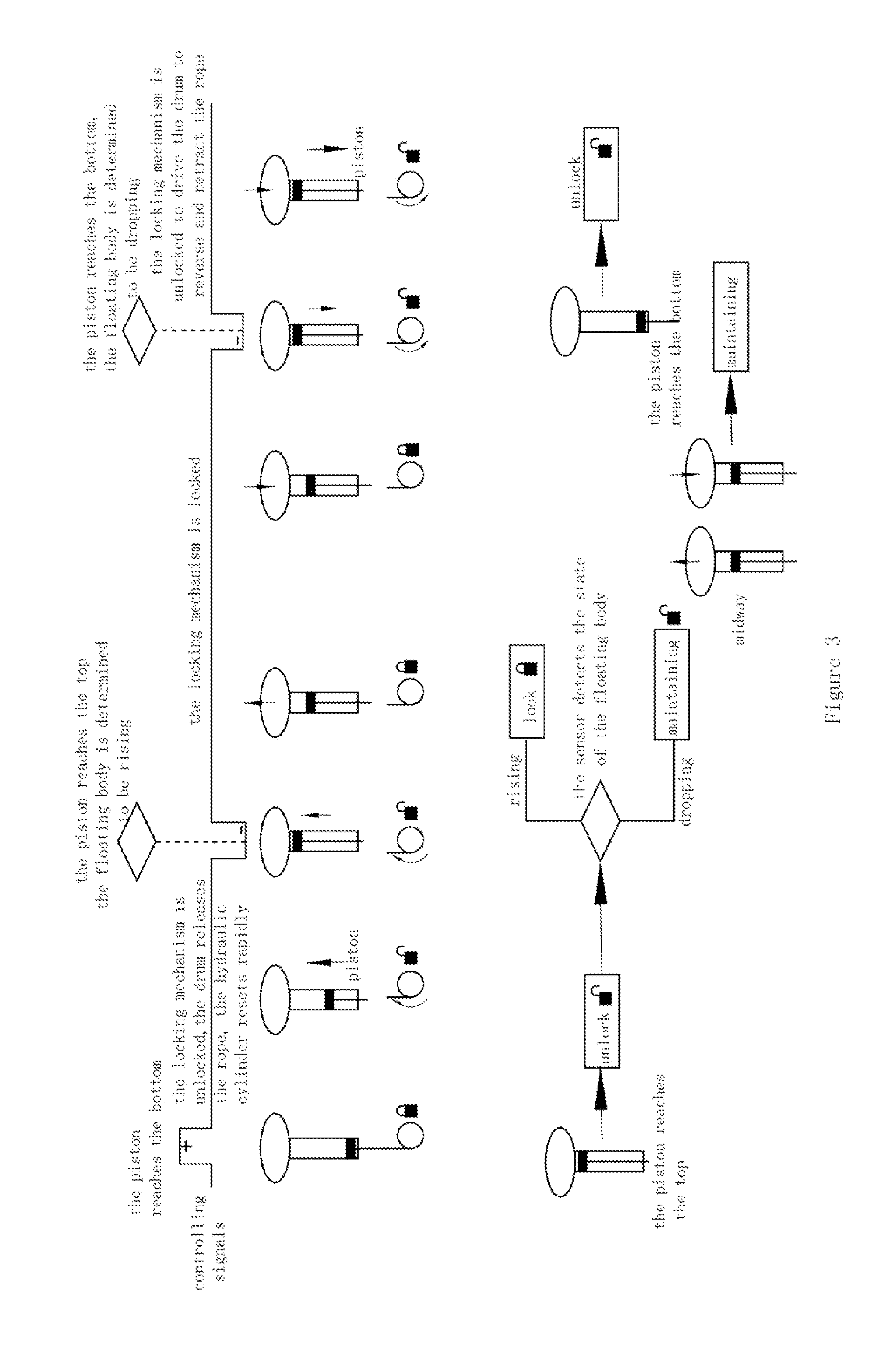
[0159]Aim: This invention aims to solve the problem of the operation of hydraulic cylinder with limited length under greater wave heights. Method: One end of the rope is attached to the piston rod of the hydraulic cylinder, which is connected to a floating body or a swinging board. The other end of the rope, together with an additional section, is connected to a rope-control device. Thus, when the floating body rises with the wave, the rope between it and the rope-control device is in a locking state. The hydraulic cylinder is being pulled as the distance between the floating body and the anchor base increases. As the latter is being pulled, it will release high-pressure hydraulic oil to drive the hydraulic motor; the hydraulic motor will in turn drive the generation of power. When the stroke action of the hydraulic cylinder is completed, it will transmit a signal to the rope-control device to release a section of the rope, at which time the hydraulic cylinder will be rapidly reset ...


PUM


Abstract

The present invention is related to a method and system for wave power generation. When a floating body rises with the wave, a hydraulic cylinder is being pulled to drive a hydraulic motor; the hydraulic motor will in turn drive the generation of power. When a stroke action of the hydraulic cylinder is completed, signals will be transmitted to a drum to release the rope, at which time the hydraulic cylinder will be reset. When the reset is completed, the distance between the floating body and the anchor base increases, the hydraulic cylinder is pulled again, thus repeating the above process. When the floating body drops along with the wave, the hydraulic cylinder is reset at first and then the drum retracts the rope. This system can automatically reset the hydraulic cylinder and do work multiple times during the process of one rising wave.

Description

CROSS REFERENCE OF RELATED APPLICATION[0001]This is a national phase national application of an international patent application number PCT / CN2012 / 082749 with a filing date of Oct. 11, 2012. The contents of the specification, including any intervening amendments thereto, are incorporated herein by reference.BACKGROUND OF THE PRESENT INVENTION[0002]1. Field of Invention[0003]The present invention is related to a method and system for wave power generation.[0004]2. Description of Related Arts[0005]Ocean wave energy is an inexhaustible and renewable energy resource. How to use this abundant energy resource for human services is always a big project in study, and the wave-power generation is a major subject in this project.[0006]Because the ocean is affected by the complex and varying natural factors, the changing size and form of the tide and the waves make it a great difficulty for people to use the energy of the ocean wave to generate stably. Over 100 years scientists from different ...

Claims


Application Information

Patent Timeline
Patent Type & Authority Applications(United States)
IPC IPC(8): B63B21/50F03B13/18B63B35/44
CPCB63B21/50B63B2035/4466F03B13/1845B63B35/44F03B13/187F03B13/189F03D3/02F03D15/00Y02E10/30Y02E10/74
Inventor QU, YANMING
Owner QU YANMING
Why Eureka
Try Eureka