
Display device

A technology for display devices and display panels, applied in identification devices, nonlinear optics, instruments, etc., can solve the problems of increasing the weight of liquid crystal display devices, limiting the thinning of liquid crystal display devices, etc., and achieve the advantages of increased rigidity and increased holding force Effect

Inactive Publication Date: 2010-09-22
SHARP KK
View PDF10 Cites 29 Cited by
  • Summary
  • Abstract
  • Description
  • Claims
  • Application Information

AI Technical Summary

Problems solved by technology

[0005] However, as in Patent Documents 1, 2, and 3, when the liquid crystal panel is sandwiched and held by frames arranged at the front and back of the liquid crystal panel, due to the increase in the depth dimension and the gap between the frame (especially the front frame portion), The amount corresponding to the configuration space limits the thinning of the liquid crystal display device, and in the case of using a metal bezel for the front frame, the liquid crystal display device becomes heavier by an amount corresponding to the weight of the bezel

Method used


Image

  • Display device
  • Display device
  • Display device

Examples


Embodiment approach 1

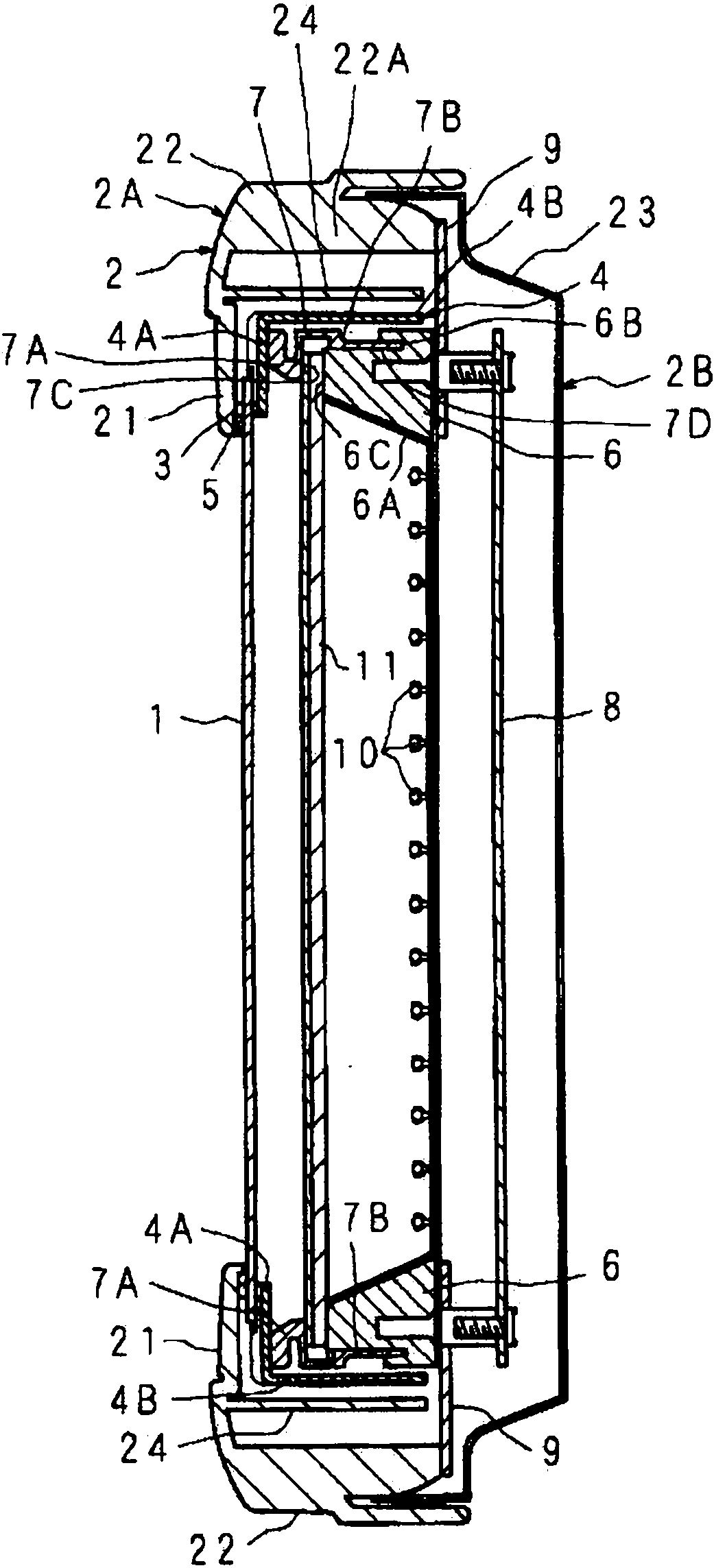
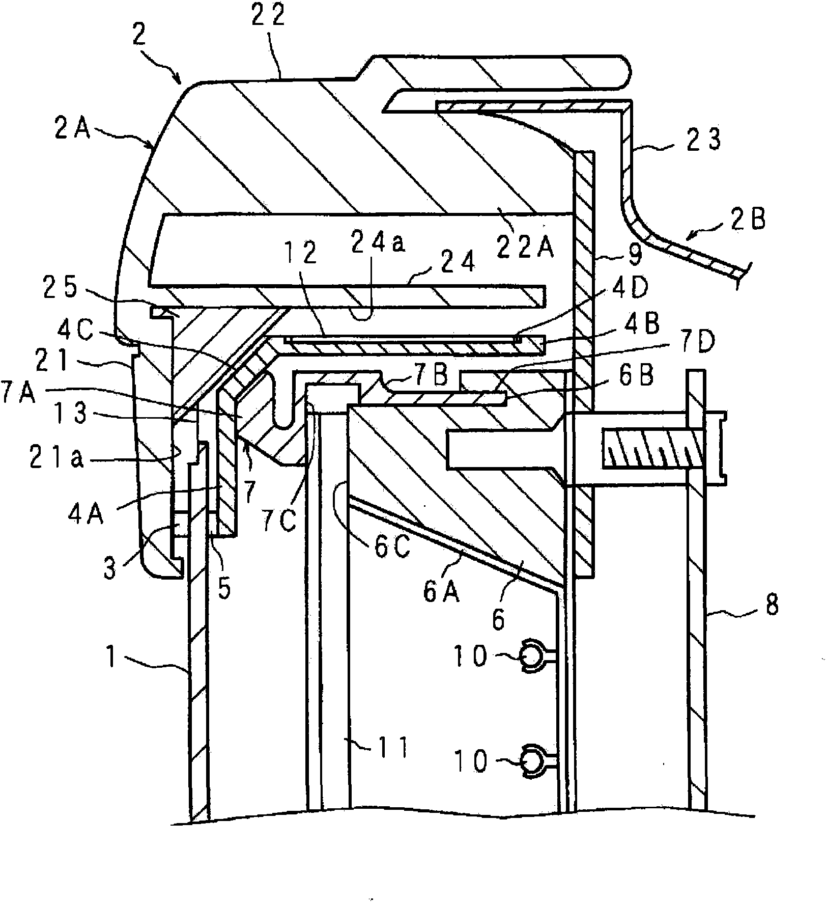
[0131] figure 1 It is a side sectional view showing the structure of the liquid crystal display device according to Embodiment 1 of the present invention. The liquid crystal display device is disposed in the space surrounded by the casing 2: a liquid crystal panel 1, which has a display surface; a backlight 10, which illuminates the liquid crystal panel 1 from the back side; and an optical sheet 11 for diffusion, The optical sheet 11 for diffusion is located between the liquid crystal panel 1 and the backlight 10 .

[0132] The case 2 is a molded product of plastic, and includes a front case 2A and a rear case 2B. The front case 2A has: a frame portion 21 having an opening formed at the center for viewing the image of the liquid crystal panel 1 from the front; The surface portion 22 is connected to the outer peripheral portion of the frame portion 21 and extends toward the rear side to cover the upper, lower, and lateral peripheral surfaces. The rear case 2B has an outer per...

Embodiment approach 2

[0144] Figure 6 It is a top cross-sectional view showing the structure of a liquid crystal display device according to Embodiment 2 of the present invention, Figure 7 yes Figure 6 A sectional view of line VII-VII, Figure 8 yes Figure 6 Sectional view of line VIII-VIII, Figure 9 yes Figure 6 A perspective view of the main part of the liquid crystal display device shown.

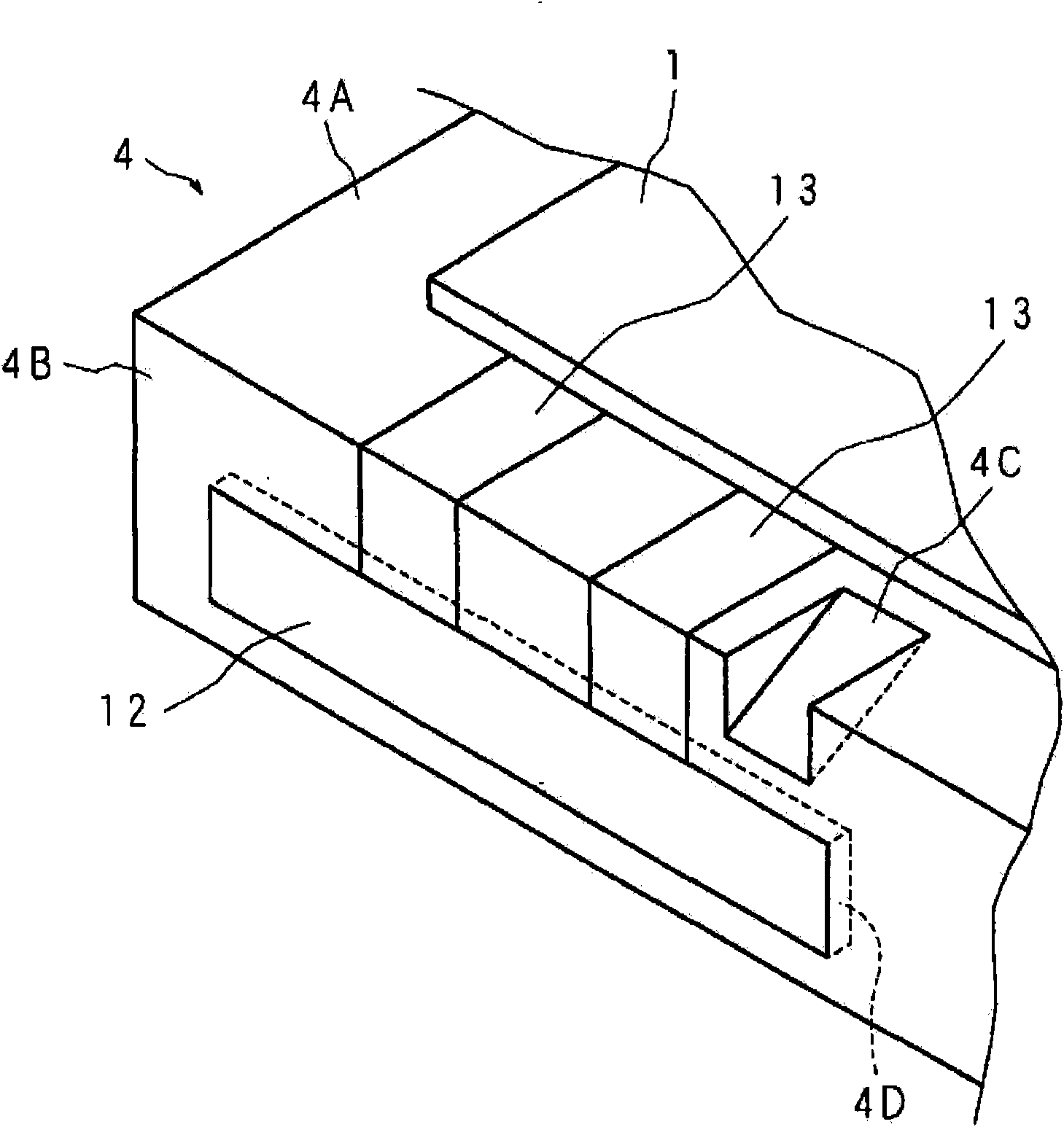
[0145] Embodiment 2 of the present invention differs from Embodiment 1 in that ribs 25A thicker than the plate thickness of the ribs 25 are provided, and that ribs 25A have cavities CV inside. A total of four ribs 25A are arranged corresponding to the vertical positions of the left and right sides of the front frame portion 4A of the frame body 4 . Similar to the first embodiment, a notch 4C1 is formed at a corner portion forming a boundary between the front frame portion 4A and the peripheral frame portion 4B of the frame body 4 so as not to interfere with each rib 25A.

[0146] The cavity CV ha...

Embodiment approach 3

[0149] Figure 10 It is a side sectional view showing the structure of the liquid crystal display device according to Embodiment 3 of the present invention, Figure 11 yes Figure 10 A rear view of a part of the structure of the liquid crystal display device shown, Figure 12 yes Figure 11 Sectional view of line XII-XII, Figure 13 yes Figure 11 Sectional view of line XIII-XIII.

[0150] In Embodiments 1 and 2 above, the ribs 25 are formed between the inner wall 21a of the frame portion 21 of the case 2 and the annular protrusion 24, but depending on the degree of rigidity of the frame portion 21 itself of the case 2, the ribs may be omitted. Object 25. In Embodiment 3 of the present invention, the difference from Embodiments 1 and 2 is that in order to omit the rib 25, the width of the ring-shaped protrusion 24 is widened to increase its rigidity, and the ring-shaped protrusion 24 has a hollow inside. CV1.

[0151] Annular protrusion 24 is a rectangular frame shape, a...


PUM


Abstract

A structure holds a display panel arranged inside a cabinet from the both sides by means of a holding member and a frame portion, which are supported by the circumferential surface section, so as to reduce thickness and frame width without using a bezel and to ensure rigidity. The cabinet is provided with a frame portion positioned on the display surface side of the display panel, a circumferential surface portion positioned at the periphery of the display panel, and a rear surface portion covering the other surface side of the display panel. A protruding section is arranged on the outer circumference side of the periphery of the display panel and the holding member to extend from the display surface side of the display panel toward the side opposite to the display surface, on an inner surface of the frame portion. A reinforcing section is arranged for connecting the inner circumference section of the protruding section with the inner surface section of a frame portion. The protruding section is provided with connecting sections, which are integrally formed with the inner surface of the frame portion, annularly arranged on the outer circumference of the display panel, and integrally formed at a plurality of positions on the protruding section in the circumference direction. The holding member has a section to be connected with the connecting section.

Description

technical field [0001] The present invention relates to a display device having a structure for holding a display panel arranged in a housing. Background technique [0002] Liquid crystal display devices such as liquid crystal televisions, which are an example of a display device having a structure for holding a display panel disposed in a housing, are characterized by light weight and thinness. The frame holds the peripheral portion of the liquid crystal panel from the front side (display surface side), and the peripheral portion of the liquid crystal panel is held by the plastic frame from the rear side (the side opposite to the display surface) (see Patent Documents 1, 2, and 3). ). The baffle located on the front side of the liquid crystal panel is used to ensure the strength of the liquid crystal panel when it is assembled in the liquid crystal display device, and the strength when the liquid crystal panel is transported between factories and within the factory during ...

Claims


Application Information

Patent Timeline
Patent Type & Authority Applications(China)
IPC IPC(8): G09F9/00G02F1/1333
CPCG02F1/133308G02F2201/465G02F2001/13332G02F2001/133317G02F2001/133311G02F1/133311G02F1/133317G02F1/13332G02F1/133322
Inventor 伊藤启太岩田英史大竹正浩
Owner SHARP KK
Learn More