Method for manufacturing a magnetoresistive sensor having a novel junction structure for improved track width definition and pinned layer stability

a manufacturing method and magnetoresistive sensor technology, applied in the field of magnetoresistive sensor manufacturing, can solve the problems of uneven material removal rate near the mask, not all ions travel in a direction, and poor track width definition, and achieve the effect of avoiding tapering

Inactive Publication Date: 2008-03-13
HITACHI GLOBAL STORAGE TECH NETHERLANDS BV
View PDF11 Cites 30 Cited by
  • Summary
  • Abstract
  • Description
  • Claims
  • Application Information

AI Technical Summary

Benefits of technology

[0023] The free layer terminates at the substantially vertical side wall, but all or a portion of the pinned layer structure extends significantly beyond the substantially vertical side walls. The extended pinned layer structure allows the sensor to posses a strong resistance to amplitude flipping while also allowing the sensor to have a very small, well defined track width.
[0027] The straight, vertical side walls and non-tapered extended pinned layer are made possible by a method of manufacture that avoids shadowing during ion milling. This method may include the formation of a tapered or dome shaped mask with no overhang or bulbous, mushroom portion. By eliminating shadowing effects, an ion mill may be performed to remove sensor material at substantially uniform rate, thereby avoiding tapering at the extended portion of the sensor.

Problems solved by technology

However, not all of the ions travel in a direction that is perfectly normal to the planes of the sensor.
This results in an uneven material removal rate near the mask.
A sloping sensor side wall results in a poorly defined trackwidth.
Unfortunately, the bulbous mask structure 110 prevents the clean accurate sensor definition.
In addition, the bulbous mask shape results in non-uniform deposition of layers such as hard bias layers and lead layers.
Since the mask structure is completely covered, a chemical lift off cannot be performed to remove the mask structure.
Although the use of a bi-layer resist allows removal of the mask without the need for CMP, it can be appreciated that the relatively large overhanging mask structure presents even greater challenges to accurate sensor definition than does the previously described CMP liftoff process, for the similar reason that the overhanging portion of the mask structure allows only a portion of the ions to pass under the overhang during the ion milling operation used to define the sensor.
Unfortunately, as the size of the sensor decreases, the magnetic characteristics of the layers making up the sensor behave less like well defined thin film structures and become unstable.
This is especially problematic with regard to the pinned layer structure.
As the track width of the sensor shrinks, the pinned layer becomes less stable.
As a result the magnetic moment of the pinned layer is prone to switching direction (amplitude flipping).
Such amplitude flipping is a catastrophic event that renders the sensor unusable.

Method used


Image

  • Method for manufacturing a magnetoresistive sensor having a novel junction structure for improved track width definition and pinned layer stability
  • Method for manufacturing a magnetoresistive sensor having a novel junction structure for improved track width definition and pinned layer stability
  • Method for manufacturing a magnetoresistive sensor having a novel junction structure for improved track width definition and pinned layer stability

Examples


Embodiment Construction

[0036] The following description is of the best embodiments presently contemplated for carrying out this invention. This description is made for the purpose of illustrating the general principles of this invention and is not meant to limit the inventive concepts claimed herein.

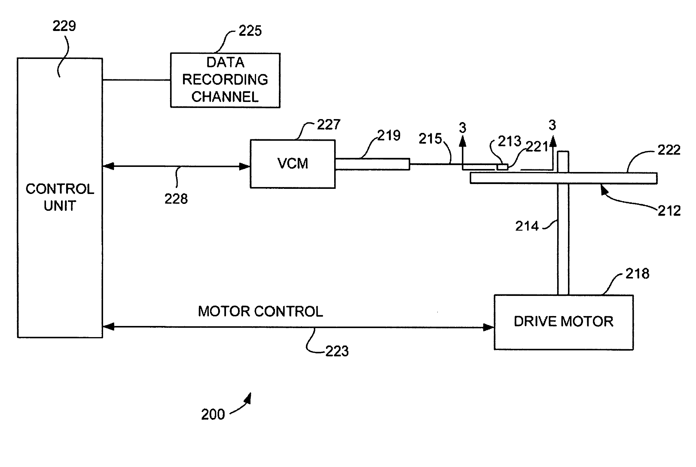
[0037] Referring now to FIG. 2, there is shown a disk drive 200 embodying this invention. As shown in FIG. 2, at least one rotatable magnetic disk 212 is supported on a spindle 214 and rotated by a disk drive motor 218. The magnetic recording on each disk is in the form of annular patterns of concentric data tracks (not shown) on the magnetic disk 212.

[0038] At least one slider 213 is positioned near the magnetic disk 212, each slider 213 supporting one or more magnetic head assemblies 221. As the magnetic disk rotates, the slider 213 moves radially in and out over the disk surface 222 so that the magnetic head assembly 221 may access different tracks of the magnetic disk where desired data are written. Each...


PUM

PropertyMeasurementUnit
poweraaaaaaaaaa
poweraaaaaaaaaa
platen poweraaaaaaaaaa

Abstract

A method for manufacturing a magnetoresistive sensor having improved pinned layer stability at small track widths. The sensor has substantially vertical side walls that define the track width of the sensor. The free layer terminates at the substantially vertical side walls, but the pinned layer structure or a portion thereof extends beyond the track width region into the field. The extended pinned layer structure provides improved resistance to amplitude flipping, while allowing the track width to remain small.

Description

RELATED APPLICATIONS [0001] This application is a Divisional Application of U.S. patent application Ser. No. 11 / 035,771 entitled MAGNETORESISTIVE SENSOR HAVING A NOVEL JUNCTION STRUCTURE FOR IMPROVED TRACK WIDTH DEFINITION AND PINNED LAYER STABILITY, filed on Jan. 14, 2005, which is incorporated by reference as if fully set forth herein.FIELD OF THE INVENTION [0002] The present invention relates to the manufacture of magnetoresistive sensors and more particularly to a method for accurately defining the side walls and track width of a magnetoresistive sensor and for improving pinned layer stability through use of a novel pinned layer structure. BACKGROUND OF THE INVENTION [0003] The heart of a computer is an assembly that is referred to as a magnetic disk drive. The magnetic disk drive includes a rotating magnetic disk, write and read heads that are suspended by a suspension arm adjacent to a surface of the rotating magnetic disk and an actuator that swings the suspension arm to plac...

Claims


Application Information

Patent Timeline
Patent Type & Authority Applications(United States)
IPC IPC(8): G11B5/33
CPCB82Y25/00G01R33/093G11B5/3903G11B5/398Y10T29/49048Y10T29/49046Y10T29/49052Y10T29/49041G11B2005/0016
Inventor FREITAG, JAMES MACJAYASEKARA, WIPUL PEMSIRIPINARBASI, MUSTAFA MICHAEL
Owner HITACHI GLOBAL STORAGE TECH NETHERLANDS BV
Why Eureka
Try Eureka