Organic light-emitting display device

a display device and light-emitting technology, applied in the field of organic temitting display devices, can solve the problems of difficult detection of accurate threshold voltages, unstable laser beam power, and difficult to achieve uniform image quality between pixel regions, so as to prevent non-uniform picture quality

Active Publication Date: 2013-04-04
LG DISPLAY CO LTD
View PDF7 Cites 31 Cited by
  • Summary
  • Abstract
  • Description
  • Claims
  • Application Information

AI Technical Summary

Benefits of technology

[0022]The embodiments are to provide an organic light-emitting display device that is adapted to prevent non-uniformity of picture quality by compensating for a threshold voltage and mobility.

Problems solved by technology

During such a crystallizing process, the power of a laser beam may be unstable.
This can cause image quality to be non-uniform between pixel regions.
In other words, in the related art method using the fixed sensing interval, it is difficult to detect accurate threshold voltages.
As such, the threshold voltages cannot be compensated for accurately.
In accordance therewith, the non-uniformity of picture quality cannot be removed.
In this case, non-uniformity of brightness caused by different threshold voltages can be removed, but it is not easy to eliminate the line mura which is caused by the variation of mobility in high gray scale levels.
Due to this, brightness defects can be caused.

Method used


Image

  • Organic light-emitting display device
  • Organic light-emitting display device
  • Organic light-emitting display device

Examples


first embodiment

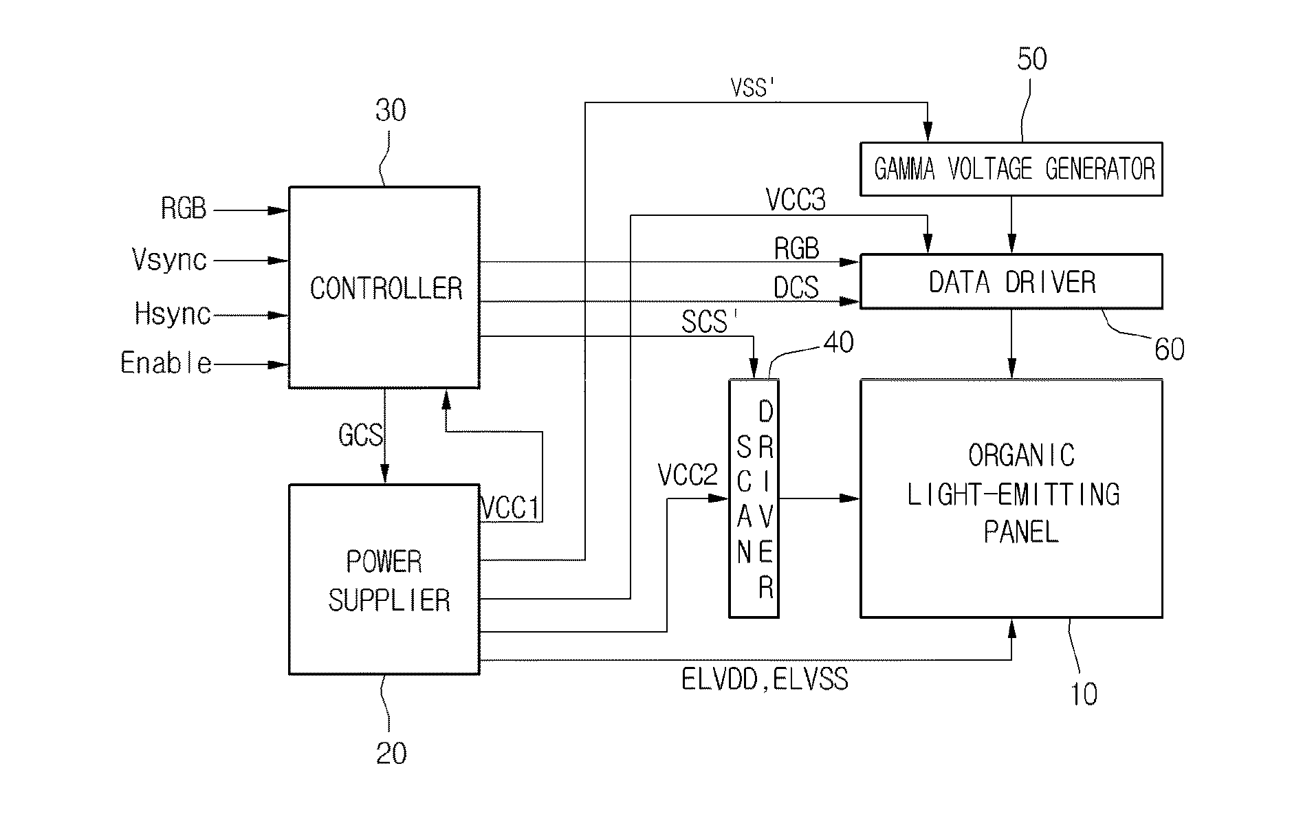
[0097]Referring to FIG. 8, the controller 30 includes an image analyzer 110, a calculator 130 and a timing controller 140. The controller 30 can further include a parameter setting unit 120 into which parameters, such as sensing Interval parameters according to gray scale levels and gamma voltage parameters according to the sensing intervals, are set.

[0098]If pixels corresponding to a high grayscale range are more than those corresponding to a low grayscale range within image of one frame, the sensing interval parameter can be set to be shortened. The sensing interval parameter to be shortened will be referred to as a first sensing interval parameter. When pixels corresponding to a high grayscale range are less than those corresponding to a low grayscale range within image of one frame, the sensing interval pamameter can be set to be lengthened. The sensing interval parameter to be lengthened will be called as a second sensing interval parameter. However, the sensing interval param...

second embodiment

[0132]More specifically, the controller 30A can avoid unnecessary computations, and furthermore reduce the computational load of a system. To this end, the controller 30A can detect an area including pixels in which a mora phenomenon is easily generated before determining large and small in the pixel numbers for the low and high grayscale ranges, and can adjust the sensing interval and the gamma reference voltage for the detected area. It is difficult to recognize the mura phenomenon in a complex area in which pixels having lots of grayscales are included. As such, it is not necessary to compute for such a complex area.

[0133]In view of this point, the controller 30A according to the second embodiment can be used to eliminate the mura phenomenon from an area including pixels in which the mura phenomenon is easily generated.

[0134]Referring to FIG. 12, the controller 30A according to the second embodiment can include a mura-recognizable area detector 200, a calculator 230, a Look-up T...


PUM


Abstract

An organic light-emitting display device includes: an organic light-emitting panel in which a plurality of pixel regions are arranged, the pixel regions each including a drive transistor configured to drive an organic light emission element and a sensing transistor configured to detect a threshold voltage of the drive transistor during a sensing interval; and a controller configured to compare a pixel number of a low grayscale range and a pixel number of a high grayscale range, which are obtained from an image signal, and adjust the sensing interval according to a compared resultant.

Description

[0001]The present application claims priority under 35 U.S.C. §119(a) of Korean Patent Application No. 10-2011-0100874 filed on Oct. 4, 2011, which is hereby incorporated by reference in its entirety.BACKGROUND[0002]1. Field of the Disclosure[0003]The present application relate to an organic t-emitting display device.[0004]2. Description of the Related Art[0005]Flat type devices for displaying information are being widely developed. The display devices include liquid crystal display devices, organic light-emitting display devices, electrophoresis display devices, field emission display devices, and plasma display devices.[0006]Among these display devices, organic light-emitting display devices have the features of lower power consumption, wider viewing angle, lighter weight and higher brightness compared to liquid crystal display devices. As such, the organic light-emitting display device is considered to be next generation display devices.[0007]Thin film transistors used in the org...

Claims


Application Information

Patent Timeline
Patent Type & Authority Applications(United States)
IPC IPC(8): G09G3/32G06F3/038G09G5/10
CPCG09G3/3233G09G2300/0819G09G2300/0861G09G2360/16G09G2320/043G09G2320/045G09G2320/0673G09G2310/0262G09G3/3258G09G3/3291
Inventor BYUN, SEUNG-CHANYI, JUNG-YOONPARK, DAE-HYEON
Owner LG DISPLAY CO LTD
Why Eureka
Try Eureka