Selective ornamentation system

Inactive Publication Date: 2013-04-18
KMMR
View PDF22 Cites 23 Cited by
  • Summary
  • Abstract
  • Description
  • Claims
  • Application Information

AI Technical Summary

Benefits of technology

[0004]Accordingly, it is an object of the present invention to provide a system

Problems solved by technology

However, once the ornamentation is no longer in favor or in fashion, the shoe (or other apparel) is typically cast aside, given away, or even thrown away.
However,

Method used


Image

  • Selective ornamentation system
  • Selective ornamentation system
  • Selective ornamentation system

Examples


Example

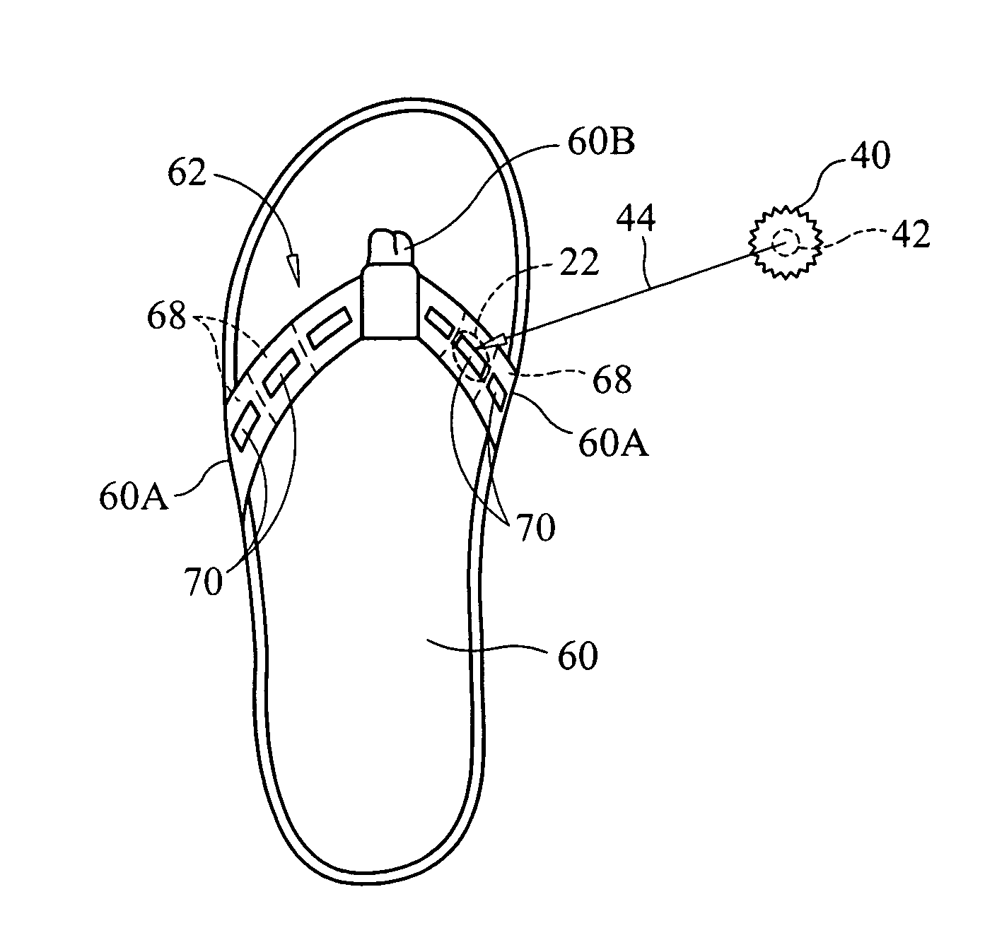
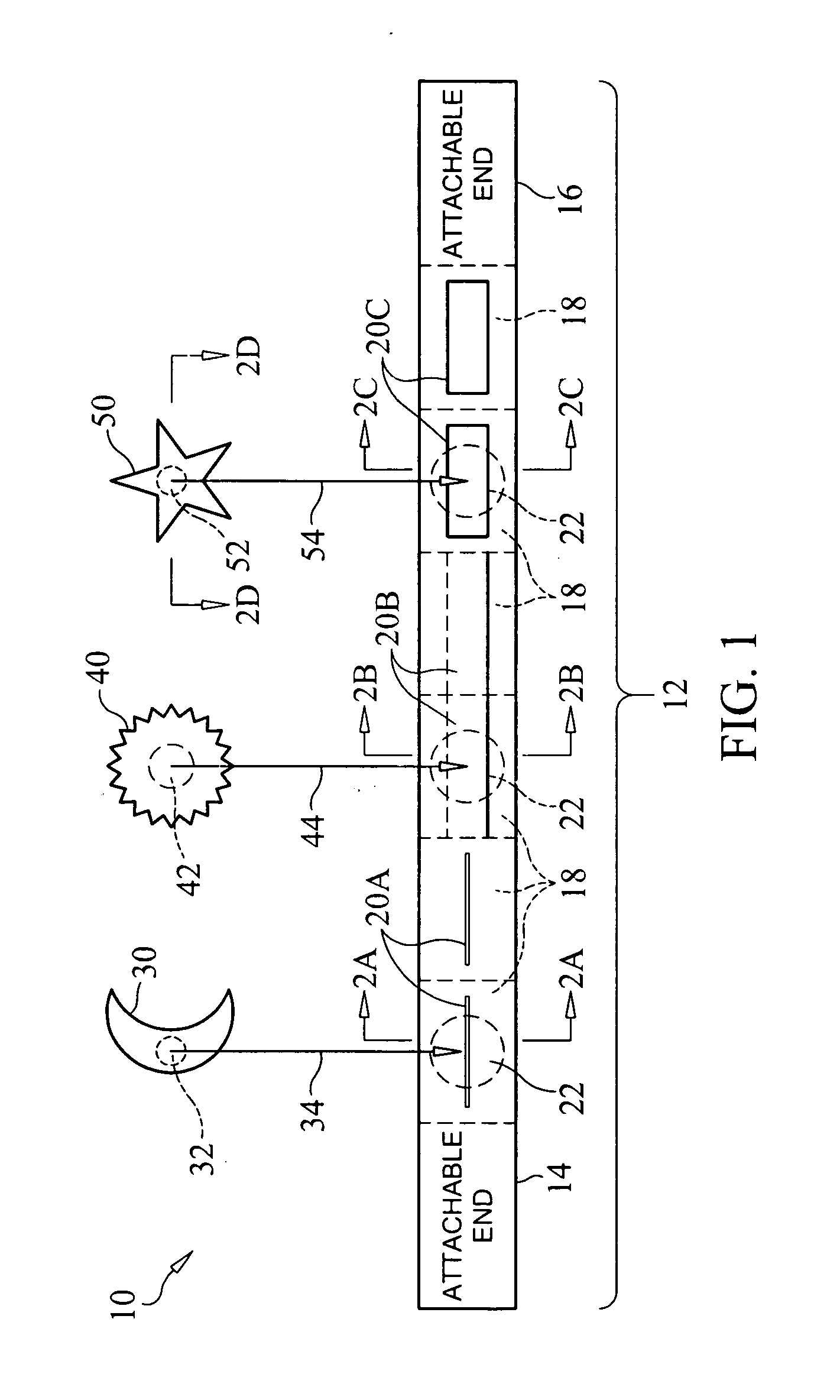
[0017]Referring now to the drawings and more particularly to FIG. 1, a decorative strap system in accordance with an embodiment of the present invention is shown and is referenced generally by numeral 10. In this embodiment, strap system 10 is configured as an article of apparel that can be purely decorative in function or provide utility as well as decoration without departing from the scope of the present invention. For example, and as will be explained later below, strap system 10 can be a purely decorative accessory added to an existing article of apparel or worn by a user. However, strap system 10 could also provide utility as well as decoration if configured as a belt, hairband, etc. Accordingly, it is to be understood that the size, shape, and materials used for strap system 10 are not limitations of the present invention.

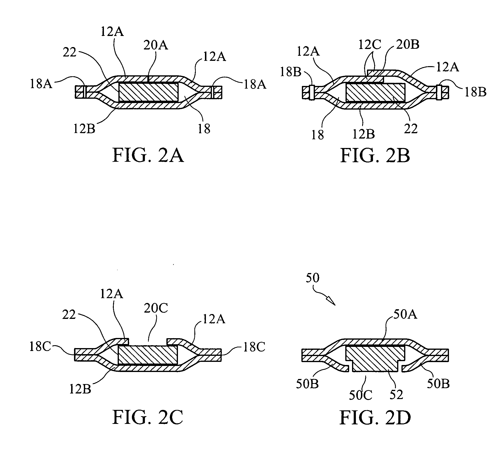
[0018]Strap system 10 includes a strap 12 having attachable ends 14 and 16. Strap 12 will typically be non-magnetic and flexible, and can be made from a var...


PUM


Abstract

A decorative strap system includes a strap with individual compartments defined therein. Each compartment is accessible via its own opening. A magnetic material piece is selectively placed in one or more of the compartments via the openings associated therewith. At least one ornament is provided where each such ornament incorporates an element for magnetic cooperation with one of the magnetic material pieces so-selectively placed.

Description

[0001]Pursuant to 35 U.S.C. §119, the benefit of priority from provisional application 61 / 382,968, with a filing date of Sep. 15, 2010, is claimed for this non-provisional application.FIELD OF THE INVENTION[0002]The invention relates generally to ornamentation for apparel, and more particularly to a system for the selective ornamentation of a strap incorporated in a piece of apparel or forming a piece of apparel.BACKGROUND OF THE INVENTION[0003]The ornamentation of shoes, boots, etc. (or other articles of apparel) can be permanently designed into a shoe (or other apparel). However, once the ornamentation is no longer in favor or in fashion, the shoe (or other apparel) is typically cast aside, given away, or even thrown away. Very often, such items will still have quite a bit of useful life left in them. To combat such premature obsolescence, some shoe designers have suggested permanently fixing magnets or magnetic materials into shoe linings at certain areas of the shoe. Ornaments i...

Claims


Application Information

Patent Timeline
IPC IPC(8): A41D27/08A43B23/24
CPCA41D27/08A45D8/34A44C25/00A43B23/24A44C5/0053A44C15/006A43B1/0054A44C17/0208A43B3/0078A44D2203/00A43B3/105A43B3/242
Inventor RANDOLPH, KRISTEN M.
Owner KMMR
Why Eureka
Try Eureka