Turbine

Inactive Publication Date: 2013-04-18
WEST 6
View PDF5 Cites 3 Cited by
  • Summary
  • Abstract
  • Description
  • Claims
  • Application Information

AI Technical Summary

Benefits of technology

[0009]It is also of compact vertical dimensions such that its visual impact on the environment is slighter.
[0010]Because of the automatic adjustment of the fluid-actives members of the rotors, the rotor position of the fluid-turbine will be optimally a

Problems solved by technology

The known wind turbine has a relatively large footprint and projects in a vertical plane with consequent negative influence on the environment.
Another disadvantage of the known wind turbine is that upon rotation, th

Method used


Image

  • Turbine
  • Turbine
  • Turbine

Examples


Embodiment Construction

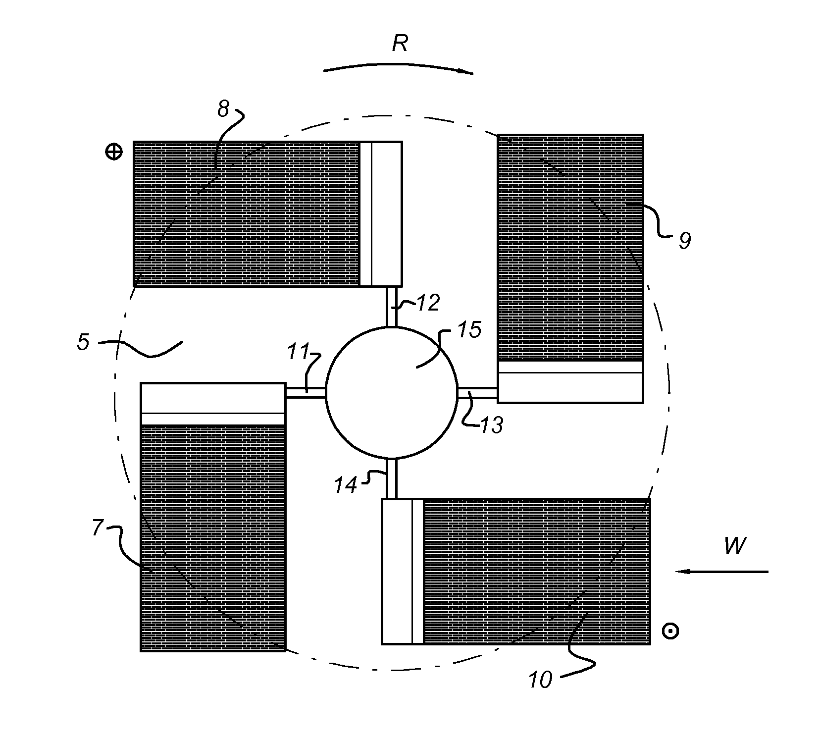
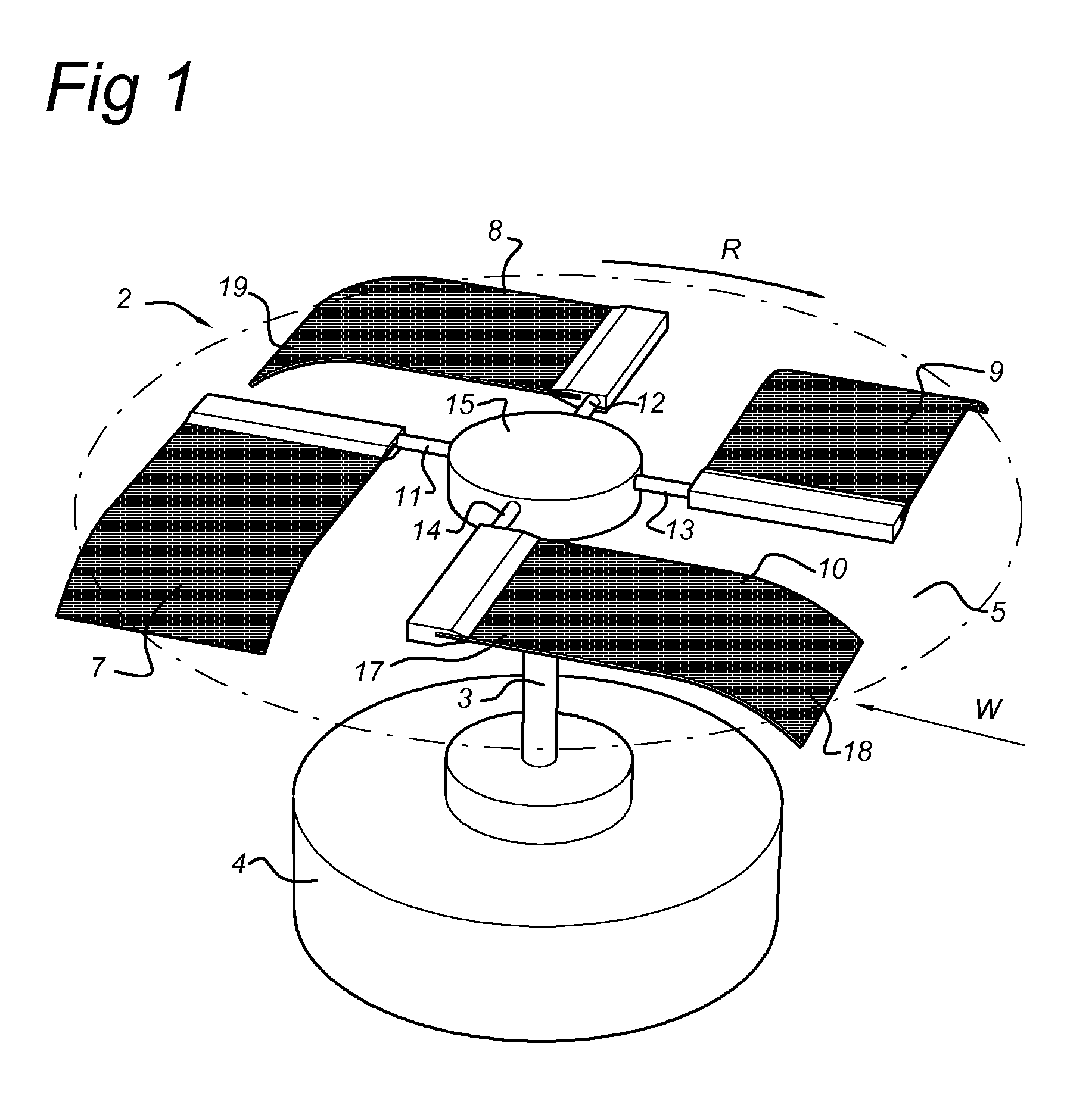
[0024]FIG. 1 shows a perspective view of an exemplary embodiment of a wind turbine 1 according to the invention, having a rotor 2 rotating in a plane of rotation 5, and attached to an axis 3. The axis 3 is connected to a drive unit 4, which may comprise an electric generator, an electric engine, a chassis on wheels, a vessel and the like. The rotor 2 is provided with four wind-contact members, or blades 7,8,9, 10, each attached via a respective arm 11,12,13,14 to a central hub 15.

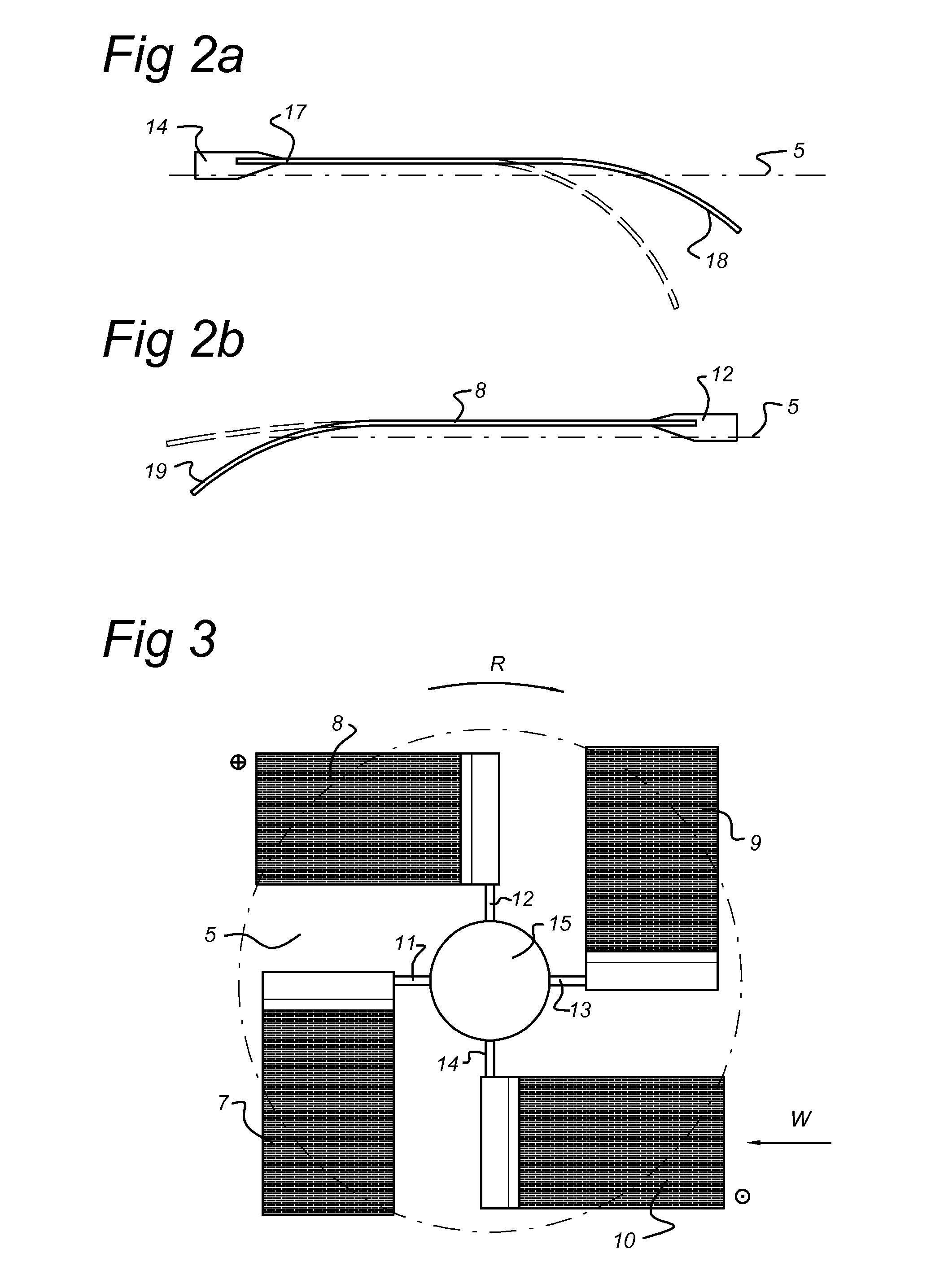
[0025]Each blade 7-10 comprises a sheet of flexible material, that is with a fixed end 17 connected to a respective arm 11-14 and which has a free end 18 which may be moved transversely to the rotational plane 5. In FIG. 1, the arms 11-14 rotate in the direction of arrow R, at a wind component in the rotational plane 5 in the direction of the arrow W. The free end 18 of blade 10 is moved downward by the force of the wind out of the rotational plane 5 while the blade 17 travels in the wind direction W. The f...


PUM


Abstract

A turbine includes a rotor having at least two rotor members for rotating in a plane, the rotor members being substantially diametrically arranged and attached to an axis situated substantially transversely to the plane, and drive unit coupled to the axis, wherein the rotor members include a fluid contact member, that is hingingly connected to an arm which is attached to the axis, characterized in that the fluid contact members are adapted to hinge between a fluid-active position in which the members project transversely to the plane and a fluid-transparent position in which the members extend mainly parallel to the plane.

Description

FIELD OF THE INVENTION[0001]The invention relates to a turbine, comprising a rotor having at least two rotor members for rotating in a plane, the rotor members being substantially diametrically arranged and attached to an axis situated substantially transversely to the plane, and drive unit coupled to the axis, wherein the rotor members comprise a fluid contact member that is hingingly connected to an arm which is attached to the axis.BACKGROUND OF THE INVENTION[0002]Such a turbine, in the particular case a vertical axis wind turbine, is known from US2010 / 0054936, showing a vertical axis wind turbine in which the wind contact members comprise airfoils that extend transversely to the plane of rotation and that can hinge around a substantially vertical axis to be aligned with the wind direction striking the surface. The known wind turbine has a relatively large footprint and projects in a vertical plane with consequent negative influence on the environment. Another disadvantage of the...

Claims


Application Information

Patent Timeline
IPC IPC(8): F01D5/02F02C7/00
CPCF03D3/005F03D3/067F05B2240/218Y02B10/30Y02E10/74F05B2220/706F02C7/00F05B2240/311F05B2220/20F05B2220/602F01D5/02
Inventor GROOT, CORNELIS
Owner WEST 6
Why Eureka
Try Eureka