Medical appliance securing device and method of using the same
a technology for securing devices and medical devices, which is applied in the direction of intravenous devices, catheters, infusion needles, etc., can solve the problems of irritating and discomforting patients, inflammation of patients' veins,
- Summary
- Abstract
- Description
- Claims
- Application Information
AI Technical Summary
Benefits of technology
Problems solved by technology
Method used
Image

Examples
first embodiment
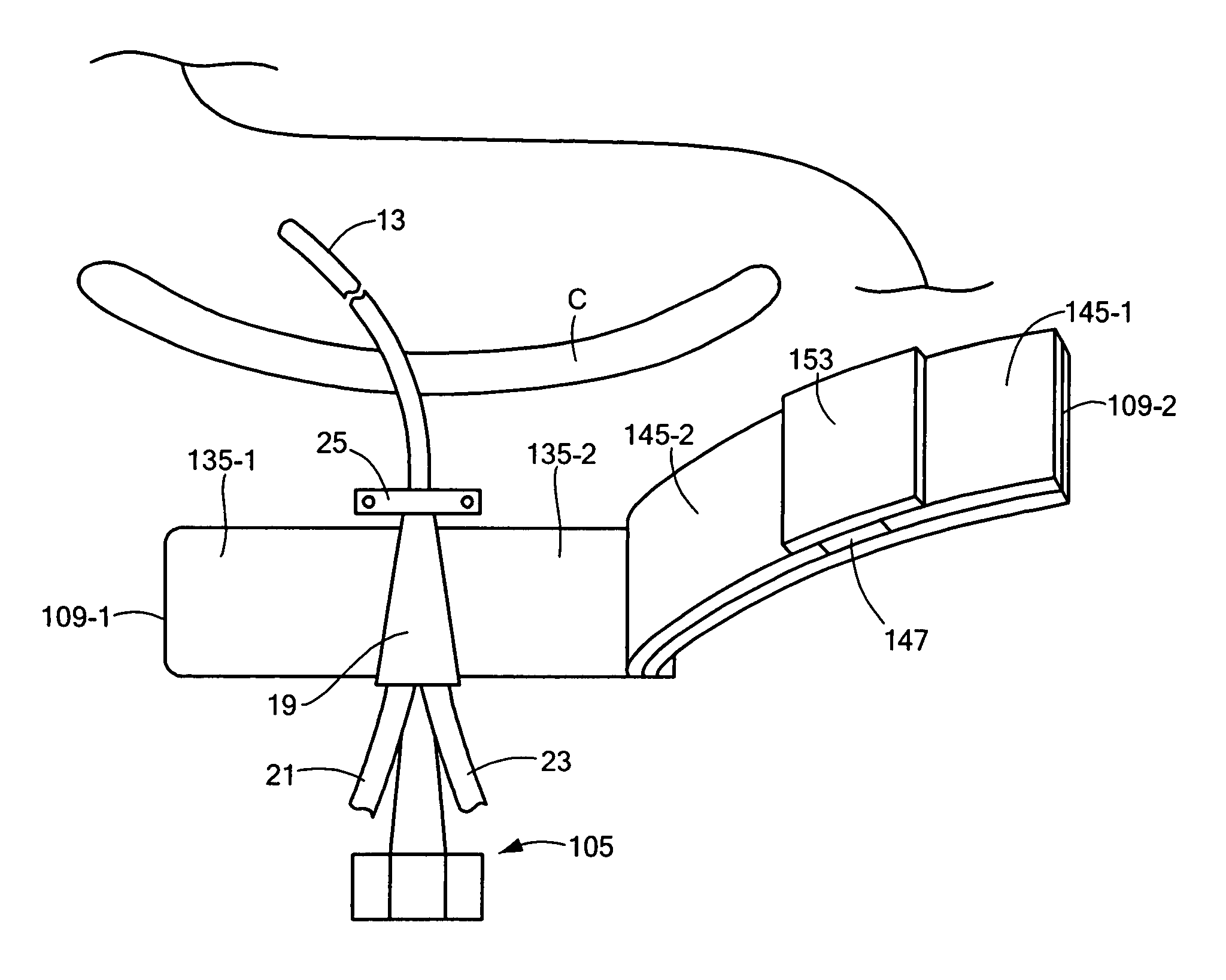
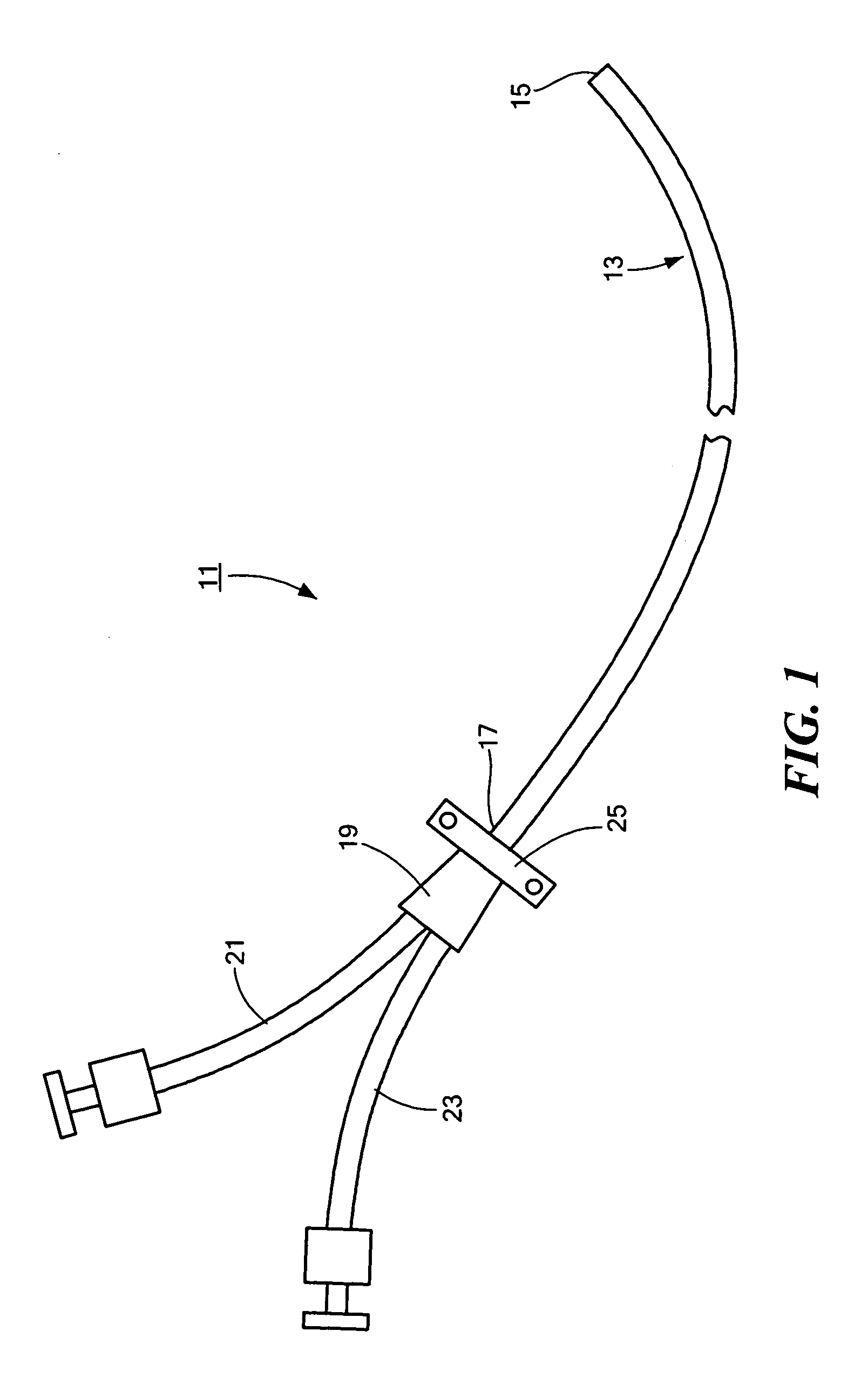
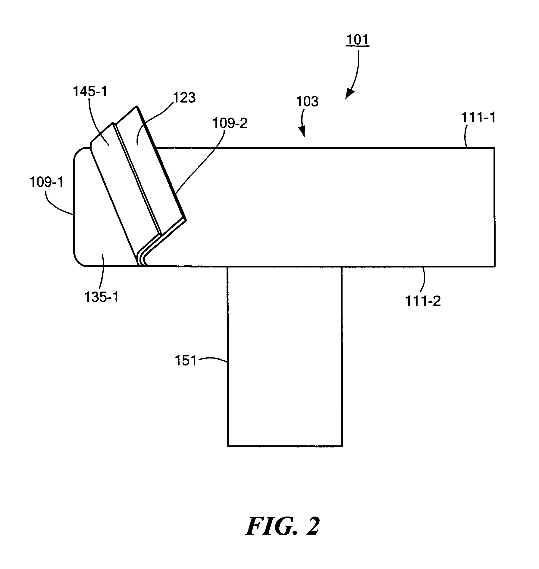
[0040]Referring now to FIGS. 2 through 5, there are shown various view of a medical appliance securing device constructed according to the teachings of the present invention, said medical appliance securing device being represented generally by reference numeral 101 (it being understood that certain components of device 101 may not necessarily be shown to scale in FIGS. 2 through 5 and that, for clarity, certain components of device 101 may not be shown in one or more of FIGS. 2 through 5). In the present embodiment, device 101 is particularly well-suited for securing a hemodialysis catheter to a patient; however, device 101 is not intended to be limited to this use and may also be used to secure other types of medical devices, particularly catheters having at least one branched end.
[0041]Device 101 may comprise a unitary, i.e., one-piece, sheet of fabric shaped to define a base 103 and a flexible strap 105. The unitary sheet of fabric used to define base 103 and strap 105 may compr...
second embodiment
[0053]Referring now to FIGS. 8(a) and 8(b), there are shown top and side views, respectively, of a medical appliance securing device constructed according to the teachings of the present invention, the medical appliance securing device being represented generally by reference numeral 201 (it being understood that certain components of device 201 may not necessarily be shown to scale and that, for clarity, certain components of device 201 may not be shown in one or both of FIGS. 8(a) and 8(b)).
[0054]Device 201 may be similar in many respects to device 101. One difference between device 201 and device 101 may be that device 201 may additionally comprise a pair of foam blocks 203-1 and 203-2. Block 203-1 may be mounted by an adhesive layer 205-1 on patch 135-1 along the edge of patch 135-1 that borders adhesive area 137. Block 203-2 may be mounted by an adhesive layer 205-2 on patch 135-2 along the edge of patch 135-2 that borders adhesive area 137. Blocks 203-1 and 203-2 may serve to ...
third embodiment
[0057]Referring now to FIG. 9, there is shown a partly exploded side view of a medical appliance securing device constructed according to the teachings of the present invention, the medical appliance securing device being represented generally by reference numeral 301 (it being understood that certain components of device 301 may not necessarily be shown to scale and that, for clarity, certain components of device 301 may not be shown).
[0058]Device 301 may be similar in many respects to device 101. One difference between device 301 and device 101 may be that, whereas device 101 may comprise first and second portions 103-1 and 103-2 that are hingedly interconnected to one another about centerline 113, device 301 may alternatively comprise base portions 303-1 and 303-2 that constitute two separate pieces.
[0059]Another difference between device 301 and device 101 may be that device 301 may additionally comprise a film 305 adhered by an adhesive layer 307 to the top surface of base port...
PUM
 Abstract
Description
Claims
Application Information
 - R&D
- Intellectual Property
- Life Sciences
- Materials
- Tech Scout
- Unparalleled Data Quality
- Higher Quality Content
- 60% Fewer Hallucinations
Browse by: Latest US Patents, China's latest patents, Technical Efficacy Thesaurus, Application Domain, Technology Topic, Popular Technical Reports.
© 2025 PatSnap. All rights reserved.Legal|Privacy policy|Modern Slavery Act Transparency Statement|Sitemap|About US| Contact US: help@patsnap.com