Friction control in hinge assembly

a technology of friction control and hinge assembly, which is applied in the direction of hinges, vehicle bodies, monocoque constructions, etc., can solve the problems of failure, stress, wear, and failure of hinge assemblies that include fewer components, and achieve the effect of reducing the number of components and reducing the number of parts

Inactive Publication Date: 2013-05-16
VENTRA GRP
View PDF8 Cites 13 Cited by
  • Summary
  • Abstract
  • Description
  • Claims
  • Application Information

AI Technical Summary

Benefits of technology

[0004]One or more embodiments of the present invention provides for a vehicle hinge assembly including a first hinge member constructed to be mounted to one of a vehicle body and a vehicle closure panel and a second hinge member constructed to be mounted to the other of the vehicle body and the vehicle closure panel. The second hinge member is pivotally connected to the first hinge member. The hinge assembly further includes a first contact member fixed to the first hinge member and a second contact member fixed to the second hinge member. The first contact member has a first surface and the second contact member has a second surface. The first contact member and the second contact member are arranged with the first and second surfaces frictionally engaged such that relative motion of the vehicle closure panel between an open position and a closed position causes relative motion between the first contact member and the second contact member to provide a frictional resistance for controlling the movement of the vehicle closure member.

Problems solved by technology

However, these hinge assemblies require many components, and thus may be more costly to manufacture and may be prone to failure, stress, and wear.
Other hinge assemblies that include fewer components may not provide consistent friction / torque throughout the range of motion of the vehicle closure member during movement between the open and closed positions.

Method used


Image

  • Friction control in hinge assembly
  • Friction control in hinge assembly
  • Friction control in hinge assembly

Examples


Embodiment Construction

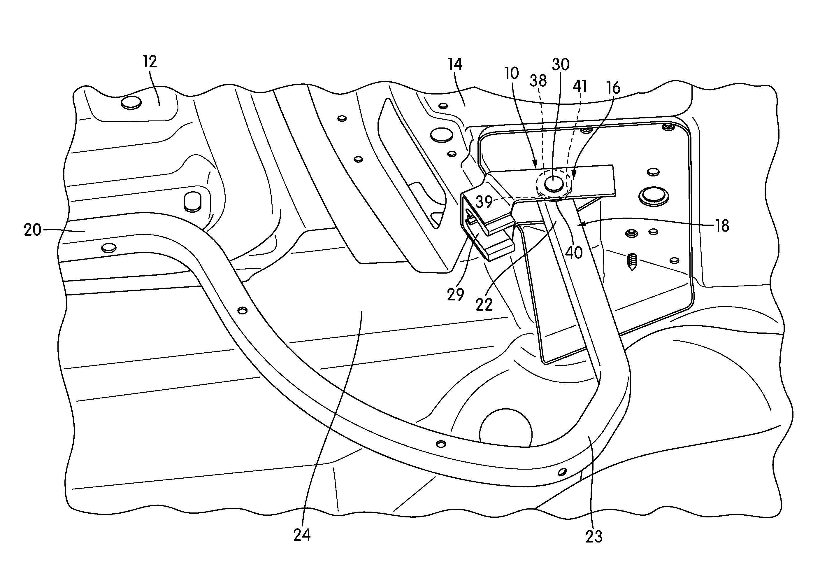
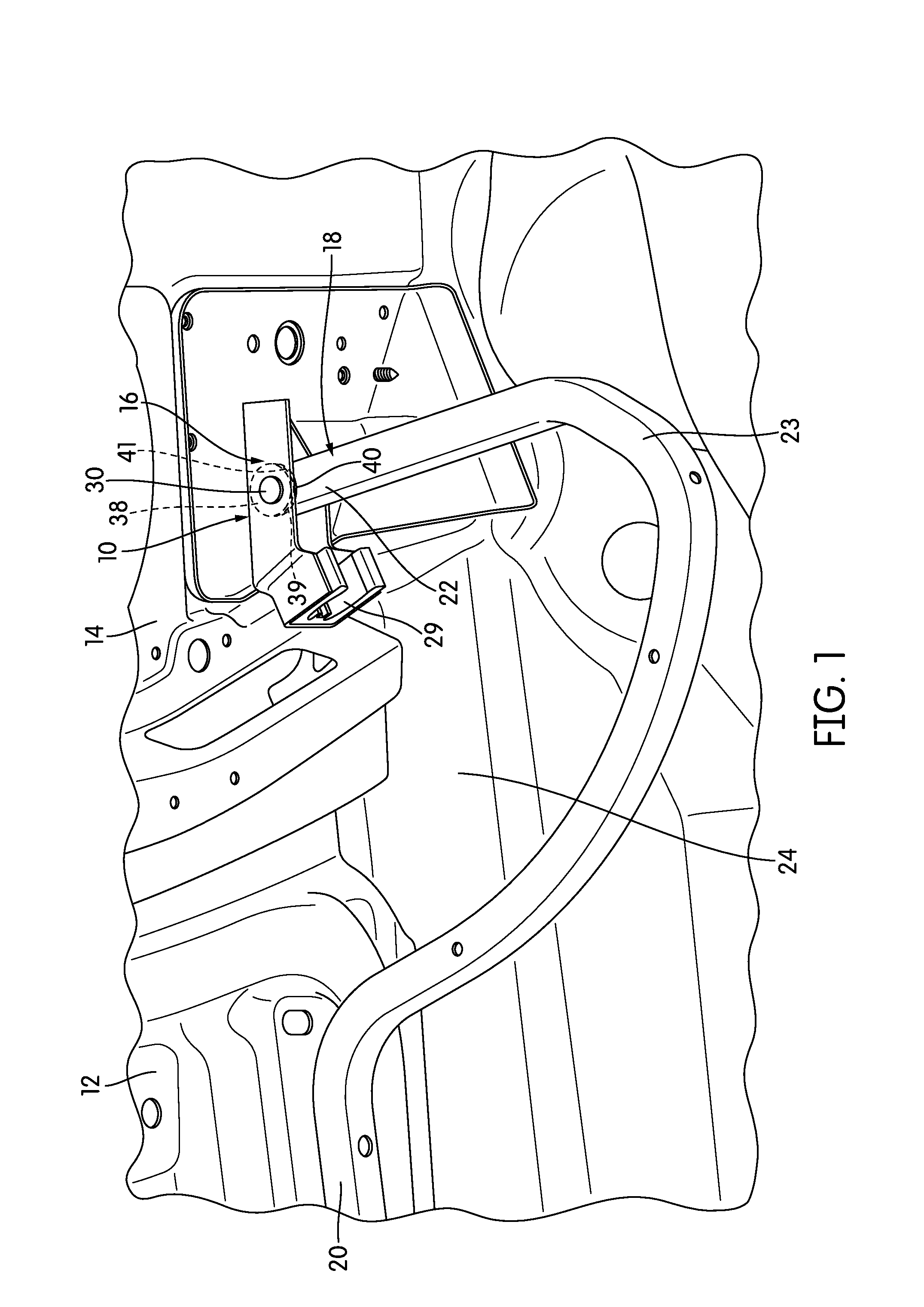
[0017]FIG. 1 illustrates an embodiment of a vehicle hinge assembly 10 that provides pivotal movement of a vehicle closure member 12, taking the form of a trunk lid in this embodiment, relative to a vehicle body 14. The vehicle closure member 12 pivots about a horizontal axis defined by the hinge axis of the hinge assembly 10. It should be appreciated that the hinge assembly 10 may be used to provide pivotal movement of other types of closure members, such as, just for example, an engine lid or a door.

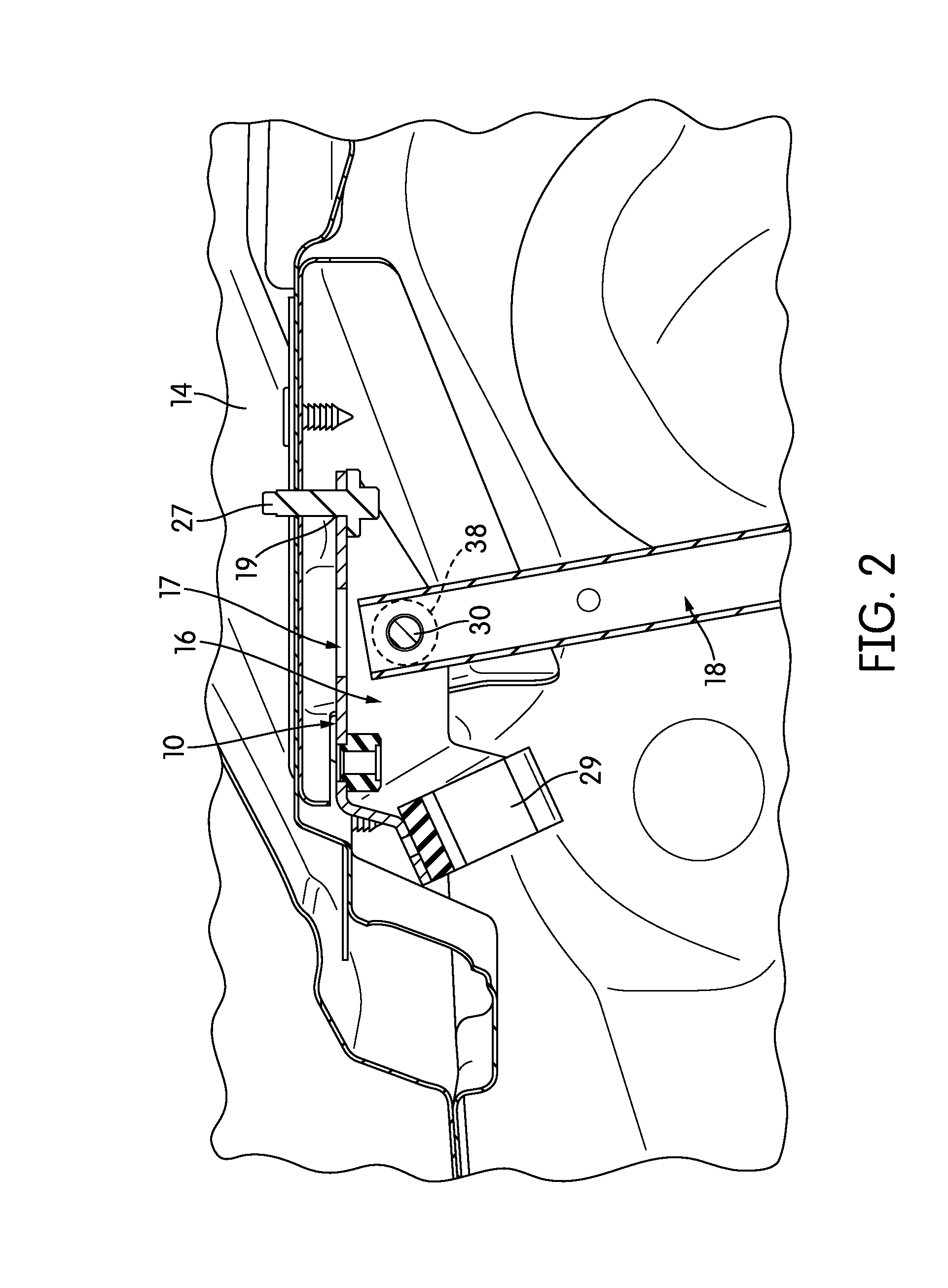
[0018]In the embodiment shown in FIG. 1, the hinge assembly 10 includes a first hinge member 16 constructed and arranged to be connected to the vehicle body 14 and a second hinge member 18 constructed and arranged to be connected to the vehicle closure member 12. In this embodiment, the first hinge member 16 takes the form of a bracket. The first and second hinge member 16, 18 may be pivotally connected to each other so as to enable the vehicle closure member 12 to pivot between a close...


PUM

PropertyMeasurementUnit
diameteraaaaaaaaaa
angleaaaaaaaaaa
frictional resistanceaaaaaaaaaa

Abstract

A vehicle hinge assembly including a first hinge member mounted to a vehicle body or a vehicle closure panel and a second hinge member mounted to the other of the vehicle body or the vehicle closure panel. A first contact member is fixed to the first hinge member and a second contact member is fixed to the second hinge member. The first contact member and the second contact member have first and second surfaces, respectively, that frictionally engage each other. The first contact member and the second contact member are arranged between the first hinge member and the second hinge member such that relative motion of the vehicle closure panel between an open position and a closed position causes relative frictional motion between the first contact member and the second contact member to provide a resistance for controlling the movement of the vehicle closure member.

Description

FIELD OF THE INVENTION[0001]The present invention relates to a hinge assembly that provides controlled pivotal movement of a vehicle closure member relative to a vehicle body.BACKGROUND[0002]Vehicle closure members, such as trunk lids, of a vehicle are pivotally connected to a vehicle body via hinge assemblies. The hinge assemblies enable the vehicle closure members to be pivoted between open and closed positions. To control the motion of the vehicle closure members during pivoting between the closed and open positions and to support the vehicle closure member at the opened state, the hinge assemblies typically include various components, such as links, rollers, torque rods, springs, and various other components that provide resilience and / or friction. However, these hinge assemblies require many components, and thus may be more costly to manufacture and may be prone to failure, stress, and wear. Other hinge assemblies that include fewer components may not provide consistent frictio...

Claims


Application Information

Patent Timeline
Patent Type & Authority Applications(United States)
IPC IPC(8): E05D7/04B21D53/40
CPCE05D5/062E05D11/087Y10T29/24E05D2005/067E05Y2900/548
Inventor PATZER, BRAD F.SMITH, MICHAEL D.J.BATTISTON, MARKDOBSON, MURRAY
Owner VENTRA GRP
Why Eureka
Try Eureka