[0015]The embodiments herein and the various features and advantageous details thereof are explained more fully with reference to the non-limiting embodiments that are illustrated in the accompanying drawings and detailed in the following description. Descriptions of well-known components and processing techniques are omitted so as to not unnecessarily obscure the embodiments herein. The examples used herein are intended merely to facilitate an understanding of ways in which the embodiments herein may be practiced and to further enable those of skill in the art to practice the embodiments herein. Accordingly, the examples should not be construed as limiting the scope of the embodiments herein.
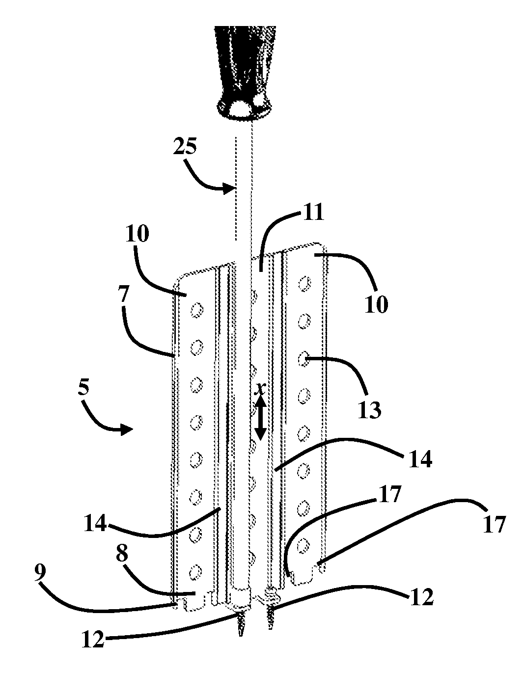
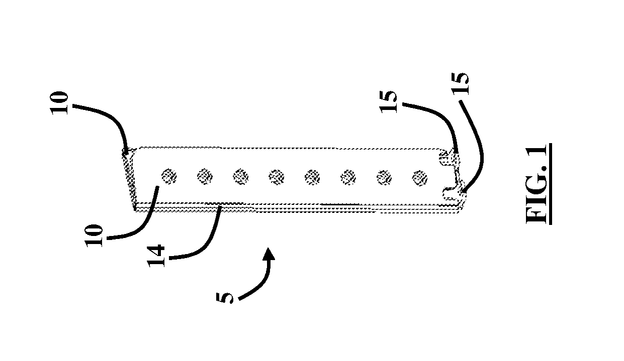
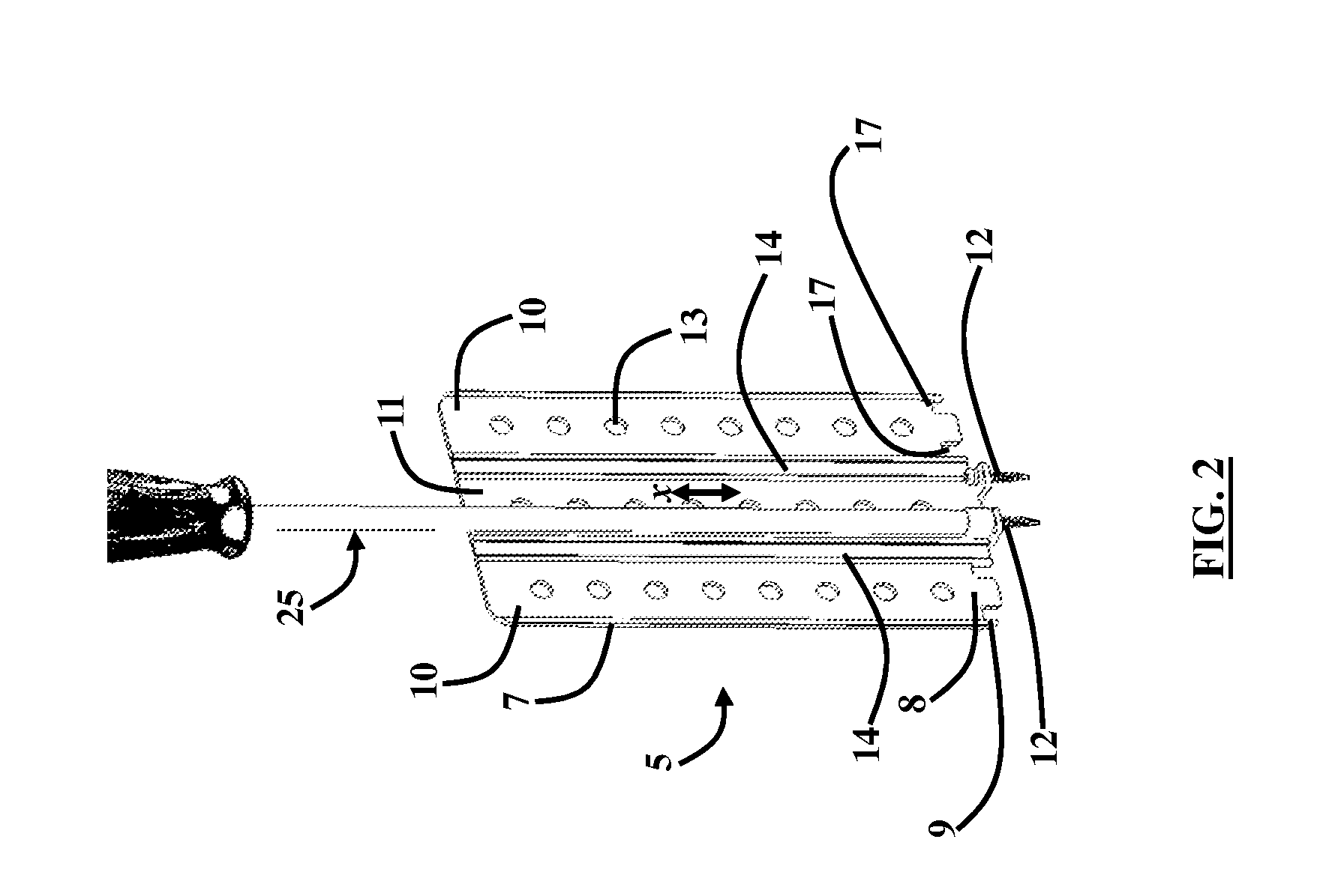
[0016]The embodiments herein provide a system and method for retracting soft tissue in the neck for purposes of performing spinal surgery using flexible walls that are fixed to bone with anchors and separated with a rigid retractor. Referring now to the drawings, and more particularly to FIGS. 1 through 5, where similar reference characters denote corresponding features consistently throughout the figures, there are shown preferred embodiments.
[0017]FIGS. 1 through 5 illustrate various views of the embodiments herein. A bone fixated retractor 5 is provided that is made of flexible material to hold its location yet is gentle on the soft tissue during retraction. The cervical retractor medical device 5 includes a plurality of panels 10, 11 comprising a middle panel 11 and a pair of flanking panels 10. A flexible region 14 (i.e., living hinge) separates the middle panel 11 from each flanking panel 10 allowing the flanking panels 10 to fold onto the middle panel 11. The flexible region 14 may be formed of a thinner material than the corresponding panels 10, 11 to cause a flexible property. In one embodiment, the flexible region 14 may include glycol-modified polyethylene terephthalate (PETG), which is a high-impact resistant co-polyester material that is a clear amorphous thermoplastic and provides high stiffness, hardness, toughness, and good impact strength. Using PETG allows the retractor 5 to be a disposable sterile packaged retractor that has a high stiffness, is inexpensive to manufacture, may be further customized in the operating room by a simple surgical scissor, and is sufficiently malleable to fold and unfold creating a living hinge. In another embodiment, all panels 10, 11 and the flexible region comprise PETG material. Moreover, variations in the width of the panels 10, 11 used for the retractor 5 can be made to allow for protection of soft tissue for differing lengths of exposure of the neck. In one embodiment, the length of each of the panels 10, 11 is approximately twice the width of the panels 10, 11 combined.
[0018]A first and second peg 15 each extends outward from a first side 2 of the middle panel 11 and in a first direction A transverse to a longitudinal axis x of the middle panel 11. A third peg 19 extends outward from a second side 3 of the middle panel 11 and in a second direction B opposite to the first direction A and transverse to the longitudinal axis x of the middle panel 11. Each flanking panel 10 comprises a tab 16 extending from a bottom portion 8 of the flanking panel 10. Also, each flanking panel 10 comprises a pair of slots 17 flanking the tab 16. The pair of slots 17 aligns with the first and second peg 15 when the flanking panels 10 fold onto the middle panel 11, and the slots 17 permit the first and second peg 15 to outwardly extend there through (i.e., through the slots 17). The tab 16 aligns between the first and second peg 15 when the flanking panels 10 fold onto the middle panel 11. An end tab 9 is positioned near the bottom portion 8 of the flanking panel 10 and along the outer edge 7 of each flanking panel 10. The end tab 9 and tab 16 defines the slot 17. Preferably, the tabs 16 are configured to terminate above the position where the pegs 15, 19 are configured to allow the tabs 16 to cross over the pegs 15 unimpeded when the flanking panels 10 are folded over the middle panel 10.
[0019]The plurality of panels 10, 11 comprises a plurality of holes 13 disposed therein. Moreover, the first, second, and third pegs 15, 19 each comprise a hole 23. The plurality of panels 10, 11 are flexible (i.e., may be formed of PETG). Furthermore, a removable bone anchor 12 (e.g., pins, screws, etc.) is adapted to connect any of the first, second, and third pegs 15, 19 to bone 21. The removable bone anchors 12 are configured to engage the holes 23 of the pegs 15, 19 to cause the connection of the device 5 to bone 21. An insertion tool 25 (e.g., a screwdriver, etc.) may be used to drive the removable bone anchor(s) 12 into the bone 21.
[0020]The impactable bone anchor 12 (e.g., pins and/or screws, etc.) may be used to secure the device 5 to the bone 21, and a rigid retractor blade 22 may be used to open these blades up further from the work area where the bone anchors 12 are driven into the bone 21 or even outside the wound (not shown) as the blades may be folded over to the side of the incision and pulled apart using a standard surgical distracter/spreader (not shown). The bone anchors 12 that keep the retractor 5 in place is a temporary feature that is removed once an implant (not shown) is in place and/or the surgery objectives are completed. These anchors 12 are removed along with the flexible blade 22. Additionally, the anchors 12 merely fix the blades to the spine and in and of themselves do not provide retraction or exposure of the spine. In one embodiment, the tabs 16 are configured to terminate above the position where the anchors 12 are positioned to allow the tabs 16 to cross over the anchors 12 unimpeded when the flanking panels 10 are folded over the middle panel 10.
[0021]The rigid retraction blade 22 that is connected to the flexible region 14 of the device 5 includes an external coupling 20 connected to the top of the blade 22, which connects to a distraction device (not shown). The back part of the blade 22 has two or more nipples (not shown) that can mate with the holes 13 in the panel 11 to maintain the connection between the blade 22 and the panel 11. The retraction blade 22 can be made of differing material as long it provides suitable rigidity to allow for retraction of the soft tissues of the neck and remains translucent to x-rays. The device 5 allows for one, two, or three blades 22 to be coupled to the panel 11 as desired by the surgeon and the clinical situation.
[0022]The embodiments herein provide single or multilevel exposure of the cervical spine with more extensive protection of soft tissue than provided by conventional cervical retraction systems. Moreover, the embodiments herein provide continuous exposure of the desired operative area with problems of retractor movement or translation due to the fixation to the spine with the small bone anchor 12 (e.g., pins and/or screws, etc.). The embodiments herein further provide decreased tension on the soft tissue from retraction during the surgery that may contribute to dysphagia and neural praxia (transient recurrent laryngeal nerve palsy). The embodiments herein may be used to provide exposure while performing an anterior lumbar interbody fusion (ALIF).
[0023]The foregoing description of the specific embodiments will so fully reveal the general nature of the embodiments herein that others can, by applying current knowledge, readily modify and/or adapt for various applications such specific embodiments without departing from the generic concept, and, therefore, such adaptations and modifications should and are intended to be comprehended within the meaning and range of equivalents of the disclosed embodiments. It is to be understood that the phraseology or terminology employed herein is for the purpose of description and not of limitation. Therefore, while the embodiments herein have been described in terms of preferred embodiments, those skilled in the art will recognize that the embodiments herein can be practiced with modification within the spirit and scope of the appended claims.