Printing system for application of a patterned clear layer for reducing gloss banding

a printing system and clear layer technology, applied in printing, other printing apparatus, printing after-treatment, etc., can solve the problems of low gloss finish of uv printers, negative impact of print quality, and relatively matte prints, etc., to reduce or eliminate negative printing effects

Active Publication Date: 2013-05-23
ELECTRONICS FOR IMAGING
View PDF3 Cites 39 Cited by
  • Summary
  • Abstract
  • Description
  • Claims
  • Application Information

AI Technical Summary

Benefits of technology

[0011]The invention involves application of a clear, low print-density after-layer of high gloss...

Problems solved by technology

In today's art, gloss finishes are commonplace with solvent based SWF printers, but a high gloss finish is not available on today's UV printers due to the fact that the curing of the droplets of UV ink leaves a matte surface structure, rather than a very smooth finish.
The relatively matte looking prints can and do suffer from a print artifact (glo...

Method used


Image

  • Printing system for application of a patterned clear layer for reducing gloss banding
  • Printing system for application of a patterned clear layer for reducing gloss banding
  • Printing system for application of a patterned clear layer for reducing gloss banding

Examples


Embodiment Construction

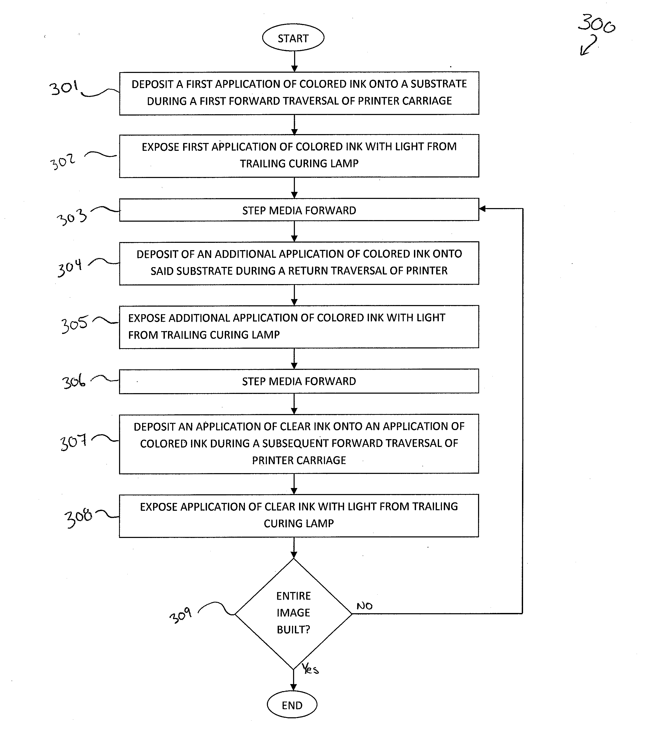
[0023]The invention is designed to essentially resolve the problem of gloss banding, without negatively impacting other critical features, such as color gamut. The invention also allows the customer to control the level of gloss such that the print artifacts are minimized.

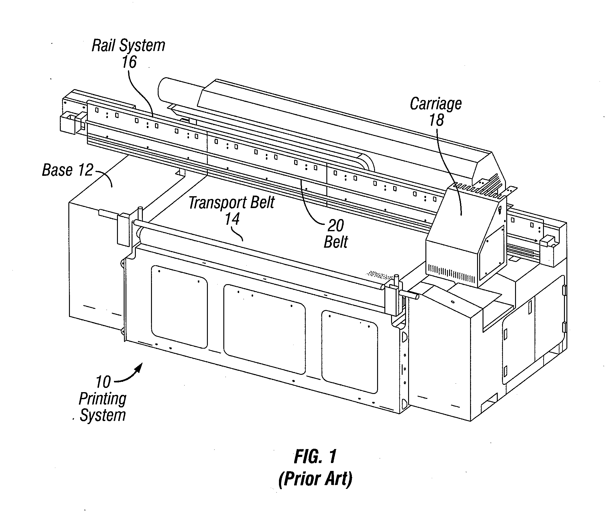
[0024]FIG. 1 is an isometric view of a prior art printing system 10, adapted for printing images on a variety of substrates. The printing system 10 includes a base 12, a transport belt 14 which moves the substrate through the printing system, a rail system 16 attached to the base 12, and a carriage 18 coupled to the rail system 16. The carriage 18 holds a series of inkjet print heads (not shown) and is attached to a belt 20 which wraps around a pair of pulleys (not shown) positioned on either end of the rail system 16. A carriage motor is coupled to one of the pulleys and rotates the pulley during the printing process. As such, when the carriage motor causes the pulley to rotate, the carriage moves linearly back an...


PUM


Abstract

The invention involves application of a clear, low-density after-layer of high gloss ink onto a printed substrate to reduce or eliminate negative printing effects, such as gloss banding. Some embodiments of the invention involve a method of applying colored ink, curing the colored ink, applying a clear ink layer in a pattern, and curing the clear layer.

Description

BACKGROUND OF THE INVENTION[0001]1. Technical Field[0002]The invention relates to ultraviolet inkjet printing. More specifically, the invention relates to the application of a visually clear, low print density after-layer of high gloss ink.[0003]2. Description of the Prior Art[0004]Inkjet printing involves depositing droplets of liquid ink onto a printing medium from one or more printer heads. The printer heads are coupled with a container containing ink. Ink is ejected from one or more nozzles of the print heads when a piezoelectric crystal in the print head is actuated. The piezoelectric crystal generates a pulse in the ink so that the ink expels through the nozzle as a droplet. To create the image, a carriage which holds one or more print heads scans or traverses across the printing medium, while the print heads deposit ink as the printing medium moves.[0005]Large format printing is performed to create signs, banners, museum displays, sails, bus boards, POP applications and the l...

Claims


Application Information

Patent Timeline
IPC IPC(8): B41J2/01
CPCB41J11/002B41J2/2114B41M7/0081B41J11/0021B41J11/00212B41J11/00218
Inventor EDWARDS, PAUL A.
Owner ELECTRONICS FOR IMAGING
Why Eureka
Try Eureka