Methods and Apparatus for Reducing Plenoptic Camera Artifacts

a technology of artifact reduction and plenoptic camera, which is applied in the direction of color television details, instruments, television systems, etc., can solve the problems of reducing the quality of the image, and reducing the artifact significantly. , the effect of reducing the artifa

Active Publication Date: 2013-05-23
ADOBE SYST INC
View PDF1 Cites 56 Cited by
  • Summary
  • Abstract
  • Description
  • Claims
  • Application Information

AI Technical Summary

Benefits of technology

[0010]Various embodiments of methods and apparatus for reducing plenoptic camera artifacts are described. The focused plenoptic camera differs from the conventional plenoptic camera in that its microlenses are focused on the photographed object rather than at infinity. The spatio-angular tradeoffs available with this approach enable rendering of final images that have significantly higher resolution than final images rendered from conventional plenoptic cameras. However, the low angular resolution of the focused plenoptic camera may result in visible artifacts when basic focused plenoptic camera rendering is used. These artifacts are a result of the basic rendering method of patching together the microimages created by the microlenses. The final image is free of artifacts in one or another part of the field at the expense of other parts of the field representing different depths in 3D.
[0014]In some embodiments, a value for a is chosen to be much greater than F2 / A. In some embodiments, “much greater than” in this expression indicates at least twice as large. In some embodiments, “much greater than” in this expression indicates at least ten times as large. Thus, to reduce artifacts in images generated from captured flats, the optics of a focused plenoptic camera may be configured so that the above relation between a and the main lens optics is satisfied.
[0018]While both the artifact-reducing focused plenoptic camera design and the artifact-reducing rendering algorithm work by themselves to reduce artifacts, the two approaches may be combined, while making tradeoffs and thus not using either to its full potential. This combined approach may provide a better position in terms of the trade-offs that are made between parallax and artifacts. At the same time, the action of both approaches reduces the artifacts significantly. This combined approach may be a practical method for 3D and refocused imaging. The final rendered images using the combined approach are of good quality and good resolution

Problems solved by technology

However, this 2-D image contains no information about the direction of the light that strikes the photosensor.
Thus, conventional cameras fail to capture a large amount of optical information.
However, the low angular resolution of the focused plenoptic camera may result in visible artifacts when basic focused plenoptic camera rendering is used.
Rendering in such a mode is rather wasteful.
Determining the magnification value Mi that provides the best match between two microimages is essentially an image registration problem.

Method used


Image

  • Methods and Apparatus for Reducing Plenoptic Camera Artifacts
  • Methods and Apparatus for Reducing Plenoptic Camera Artifacts
  • Methods and Apparatus for Reducing Plenoptic Camera Artifacts

Examples


example results

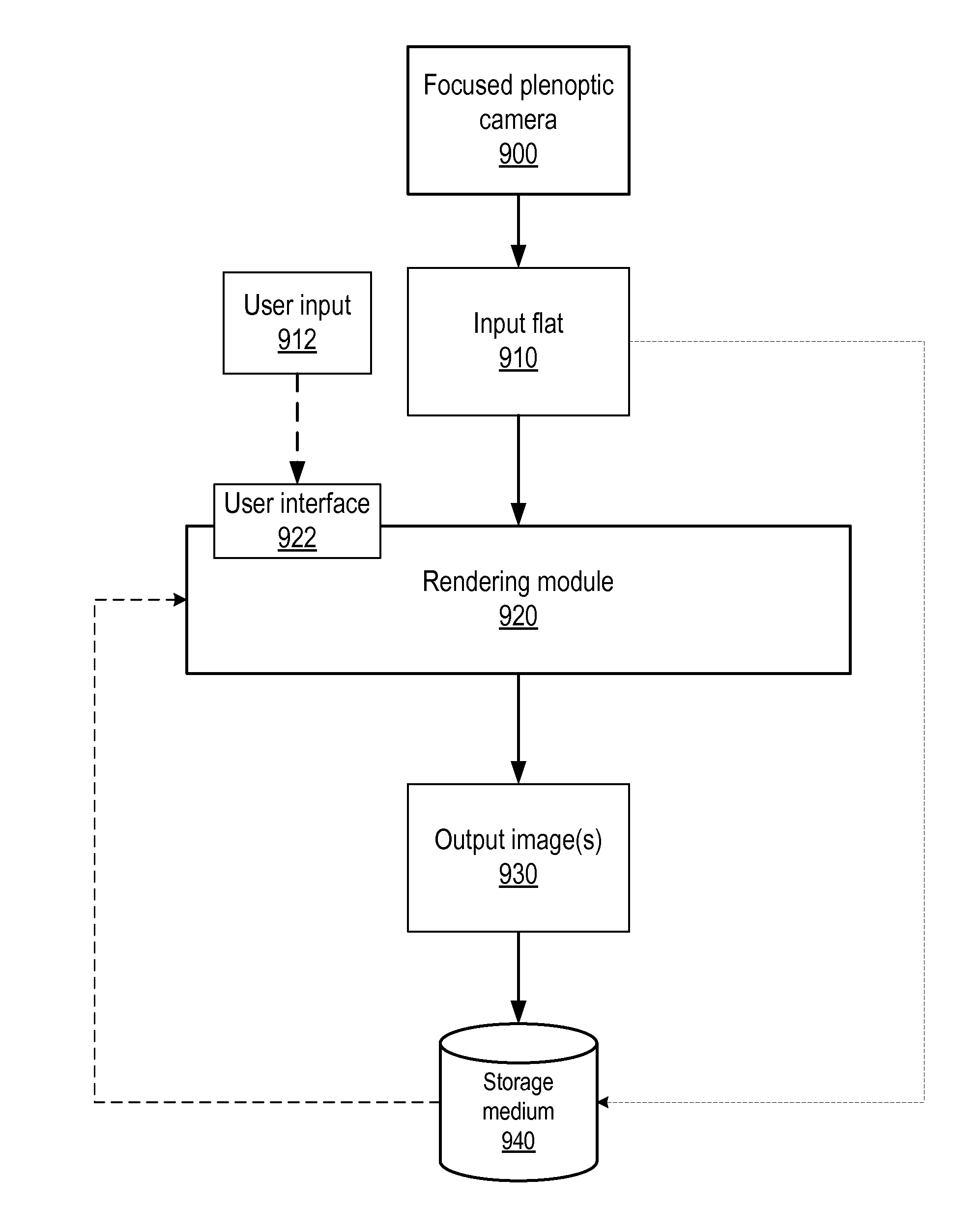
[0189]The section Example focused plenoptic camera implementation introduced an example implementation of a focused plenoptic camera. For the example focused plenoptic camera implementation, a medium format camera, using an 80-mm lens and a 39-megapixel digital back, is used. Pixel size is 6.8 μm. The lens is mounted on the camera with a 13 mm extension tube, which provides the needed spacing to establish an appropriate distance from the focal plane to the microlens array and the sensor. The rationale for the extension as a way of reducing artifacts was described in the above-noted section. In the example focused plenoptic camera, the microlens array works with the sensor without removing the cover glass. For that purpose, the microlenses have focal length of 1.5 mm and the array is placed directly on the cover glass of the sensor, after removing the infrared filter. The microlenses are spaced 0.5 mm apart. With this configuration, the microlens array matches a main lens F-number as...


PUM


Abstract

Methods and apparatus for reducing plenoptic camera artifacts. A first method is based on careful design of the optical system of the focused plenoptic camera to reduce artifacts that result in differences in depth in the microimages. A second method is computational; a focused plenoptic camera rendering algorithm is provided that corrects for artifacts resulting from differences in depth in the microimages. While both the artifact-reducing focused plenoptic camera design and the artifact-reducing rendering algorithm work by themselves to reduce artifacts, the two approaches may be combined.

Description

PRIORITY INFORMATION[0001]This application is a continuation of U.S. application Ser. No. 12 / 690,871, filed Jan. 20, 2010, which claims benefit of priority of U.S. Provisional Application Ser. No. 61 / 145,923 entitled “Reducing Plenoptic Camera Artifacts” filed Jan. 20, 2009, the content of which is incorporated by reference herein in its entirety.BACKGROUNDDescription of the Related Art[0002]In a conventional camera, the main lens maps the 3D world of the scene outside camera into a 3D world inside camera. FIG. 1 illustrates imaging in a conventional camera. “Inside world” represents inside the camera. The shaded oval regions represent the order of depths in the outside world, and the corresponding depths inside the camera. One particular image plane inside the camera is shown. The mapping of the 3D world of the scene outside camera into a 3D world inside camera is governed by the lens equation:1A+1B=1Fwhere A and B are respectively the distances from the lens to the object plane an...

Claims


Application Information

Patent Timeline
Patent Type & Authority Applications(United States)
IPC IPC(8): H04N5/262H04N5/225H04N13/232
CPCH04N5/2254G02B27/1066H04N13/232H04N23/957H04N23/635
Inventor GEORGIEV, TODOR G.LUMSDAINE, ANDREW
Owner ADOBE SYST INC
Why Eureka
Try Eureka