Apparatus for wireless device charging using radio frequency (RF) energy and device to be wirelessly charged

a wireless device and radio frequency energy technology, applied in the direction of transportation and packaging, transportation and packaging, and the arrangement of several simultaneous batteries, can solve the problem of difficulty in sealing the enclosure of the device to provide a watertight or water resistant packag

Inactive Publication Date: 2013-06-06
QUALCOMM INC
View PDF14 Cites 293 Cited by
  • Summary
  • Abstract
  • Description
  • Claims
  • Application Information

AI Technical Summary

Problems solved by technology

One problem with a wired charging arrangement is that the device to be charged must include a connector port to which a corresponding connector on the charger i

Method used


Image

  • Apparatus for wireless device charging using radio frequency (RF) energy and device to be wirelessly charged
  • Apparatus for wireless device charging using radio frequency (RF) energy and device to be wirelessly charged
  • Apparatus for wireless device charging using radio frequency (RF) energy and device to be wirelessly charged

Examples


first embodiment

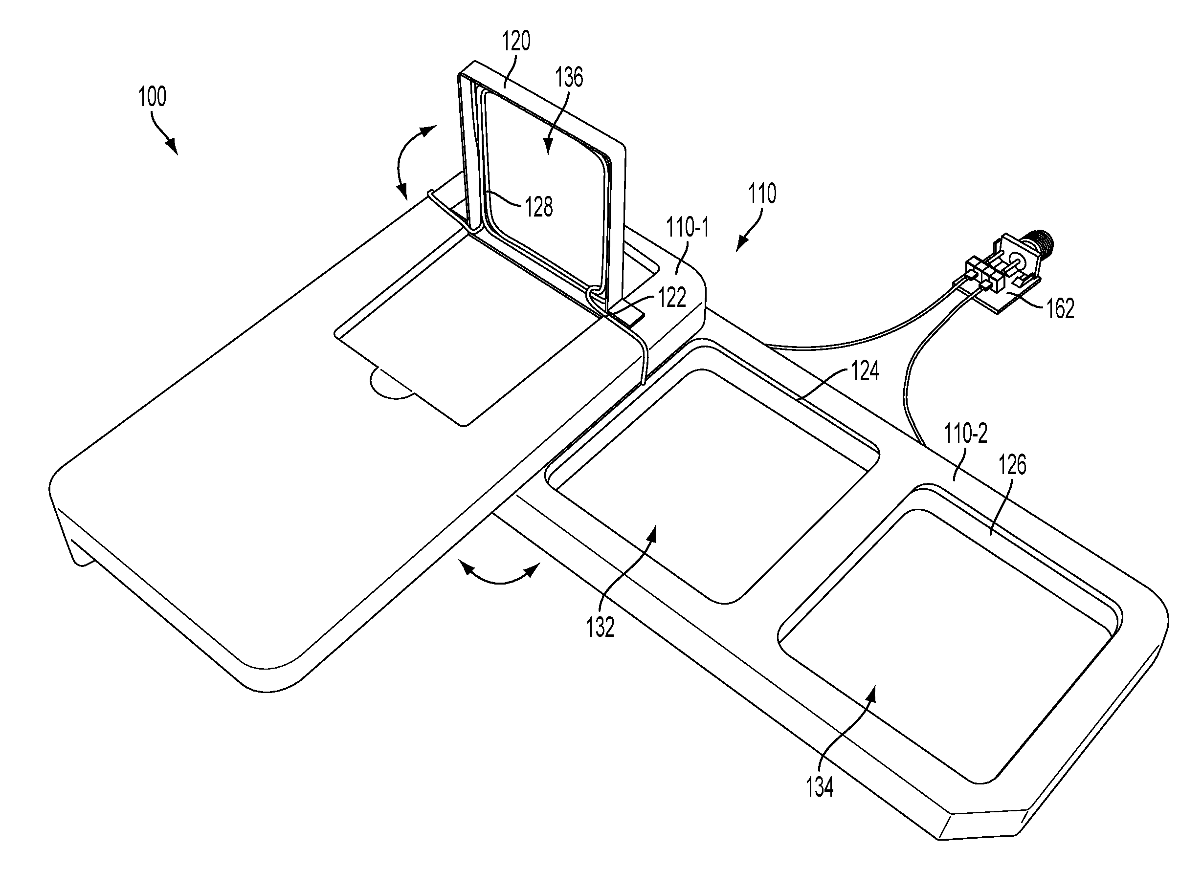
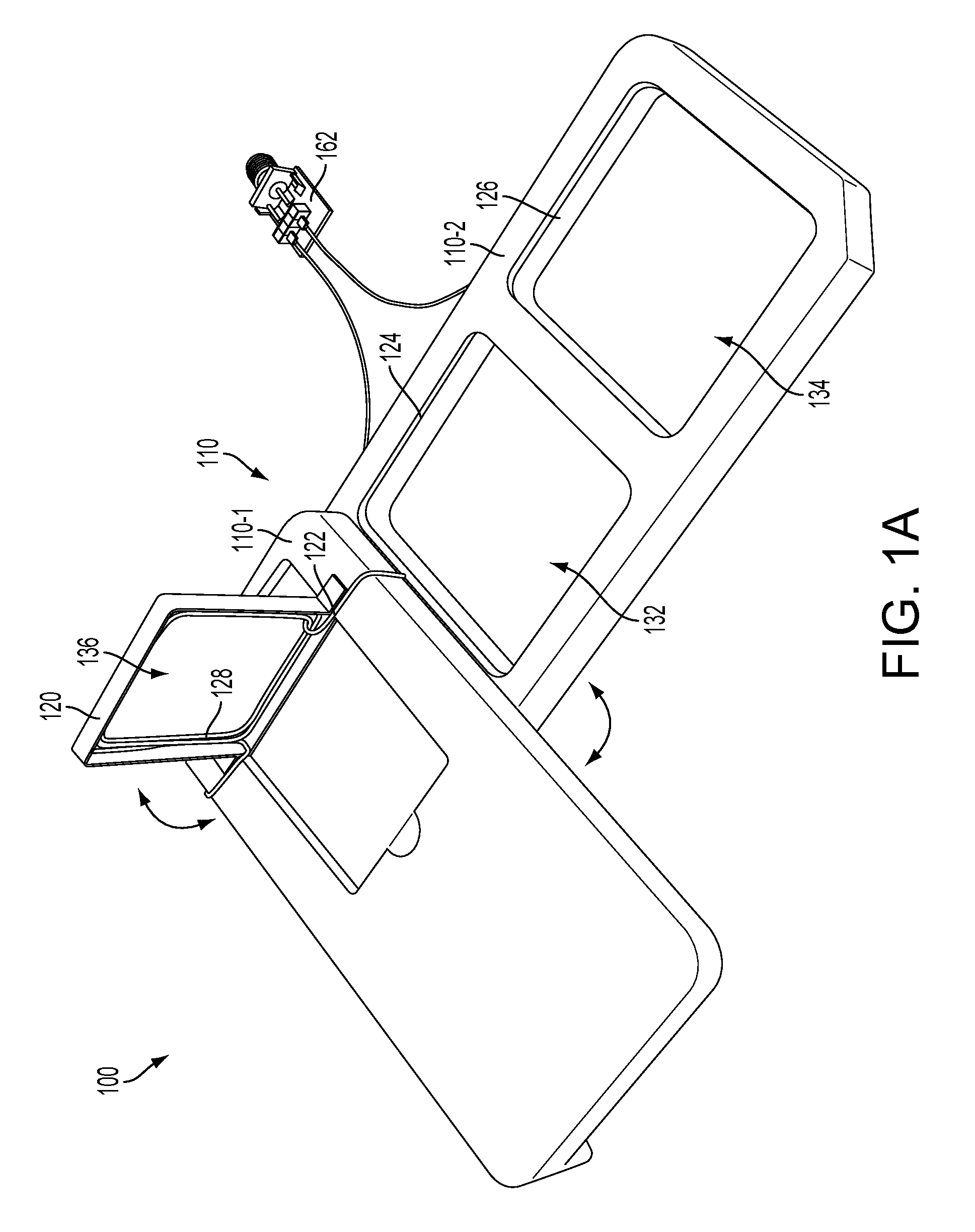
[0028]FIG. 1A is a schematic diagram illustrating a wireless charger 100. The wireless charger 100 comprises a first charger portion 110 and a second charger portion 120. In an embodiment, the first charger portion 110 comprises a first element 110-1 and a second element 110-2, which may be movably coupled together, for instance, rotatably coupled together at a pivot axis (not shown). In an embodiment, the element 110-1 and the element 110-2 can rotate about the pivot point so they can be collapsed together or opened as shown in FIG. 1A.

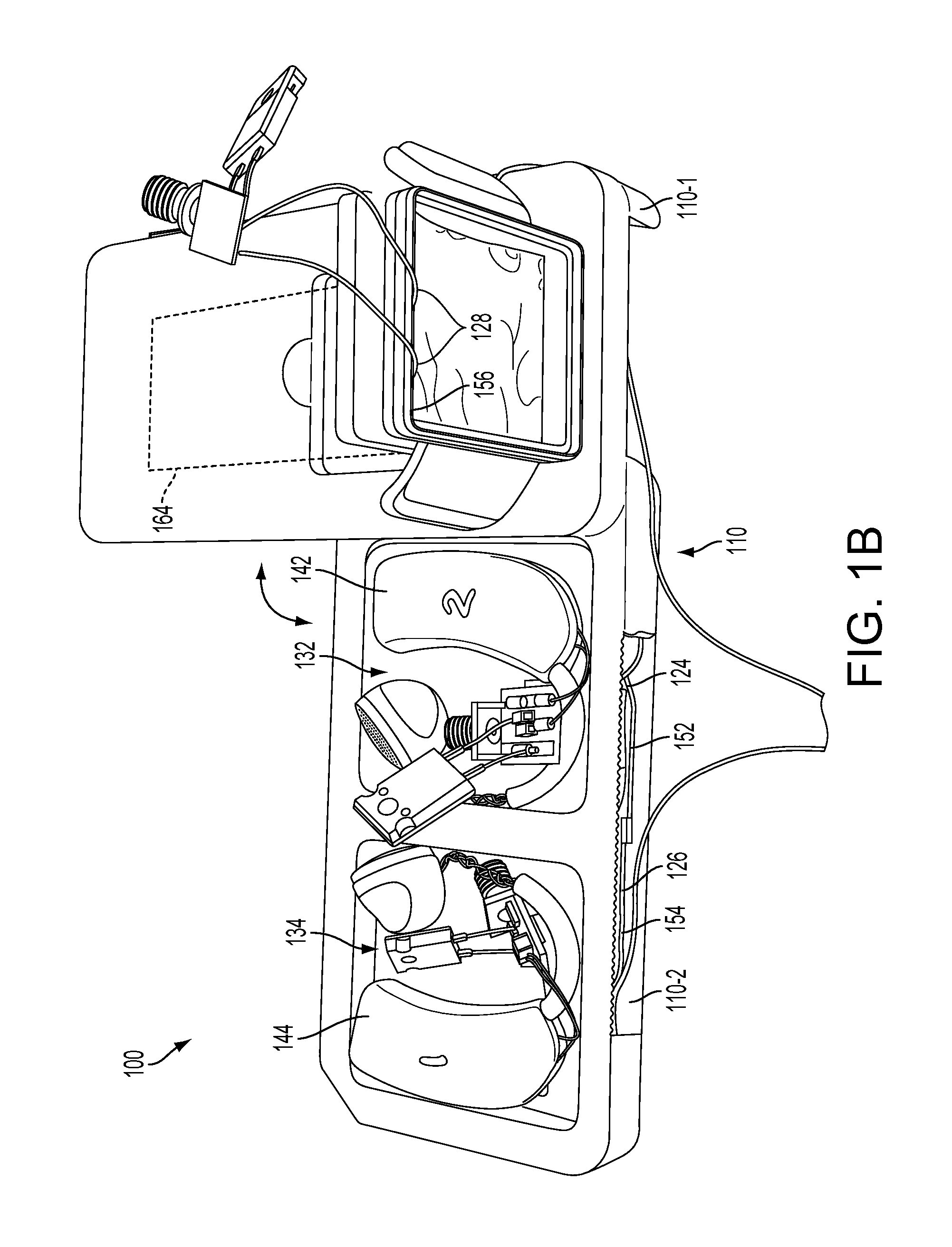
[0029]In an embodiment, the element 110-2 of the first charger portion 110 may be adapted for charging ear-worn devices and the second charger portion 120 may be adapted for charging wrist-worn devices. The second charger portion 120 may be located adjacent to the element 110-1 of the first charger portion 110 using a hinge 122. The hinge 122 may allow the major axis of the second charger portion 120 to be rotated to a position that is substantially ...

second embodiment

[0035]FIG. 2A is a schematic diagram illustrating a wireless charger. The wireless charger 200 comprises a first charger portion 210 and a second charger portion 220. In an embodiment, the first charger portion 210 may be adapted for charging ear-worn devices and the second charger portion 220 may be adapted for charging wrist-worn devices. The second charger portion 220 may be located adjacent to the first charger portion 210 using a hinge 222. The hinge 222 may allow the major axis of the second charger portion 220 to be rotated to a position that is substantially orthogonal to the major axis of the first charger portion 210.

[0036]FIG. 2B illustrates an alternative view of the wireless charger of FIG. 2A. The wireless charger 200 shows the second charger portion 220 being rotated to a vertical position on the hinge 222 so that a major axis of the second charger portion 220 is substantially orthogonal to a major axis of the first charger portion 210.

[0037]The first charger portion ...


PUM


Abstract

An apparatus for wireless charging using radio frequency (RF) energy includes a first charger portion having first and second charging areas. The first and second charging areas are located in a common plane, each having at least one coil for wirelessly charging a charge-receiving device placed in proximity thereto. The coils include respective windings, which are wound in opposing directions, each coil being connected in series, each coil configured to charge at least one charge-receiving device. A second charger portion has a third charging area having at least one coil including a winding for wirelessly charging a charge-receiving device placed in proximity to the third charging area, the coil in the third charging area being connected in series with the coils in the first and second charging areas, the third charging area located in a plane that is orthogonal to the plane of the first and second charging areas.

Description

CROSS-REFERENCE TO RELATED APPLICATIONS[0001]This application claims priority to, and the benefit of, U.S. Provsional Patent application No. 61 / 566,894, filed Dec. 5, 2011, entitled “APPARATUS FOR WIRELESS DEVICE CHARGING USING RADIO FREQUENCY (RF) ENERGY AND DEVICE TO BE WIRELESSLY CHARGED,” the entire disclosure of which is hereby incorporated into this document by reference.DESCRIPTION OF THE RELATED ART[0002]Portable communication devices, such as cellular telephones, are frequently used with wireless headsets, and other small form factor devices. Further, it is envisioned that there are applications for portable communication devices that will distribute the functionality of a portable cellular telephone over smaller devices. One such application is the use of a small, wrist-worn device that can be paired with a wireless headset or earpiece to function as a portable cellular telephone. Other device functionality, such as GPS-based location and navigation, and other functionalit...

Claims


Application Information

Patent Timeline
IPC IPC(8): H02J7/00
CPCH02J7/025H02J5/005H02J50/10H02J7/0013H02J7/0044H02J50/402H02J50/005H02J50/20H02J50/40H04B5/0037H04B5/0087H02J7/0042
Inventor JENWATANAVET, JATUPUMOZAKI, ERNEST T.LOW, ZHEN NING
Owner QUALCOMM INC
Why Eureka
Try Eureka