Communication unit, communication system, communication method, and recording medium

a communication system and communication unit technology, applied in the field of communication units, can solve problems such as taking tim

Inactive Publication Date: 2013-06-06
NEC CORP
View PDF7 Cites 18 Cited by
  • Summary
  • Abstract
  • Description
  • Claims
  • Application Information

AI Technical Summary

Benefits of technology

[0009]An object of the present invention is to provide a communication unit, a communication system, a communication method, and a communication program, which can solve the above-mentioned.
[0014]According to the present invention, it becomes possible to switch the route at high speed by a control server according to the communication state of the network,

Problems solved by technology

In the above-mentioned method, however, there is a problem to take time until new route is set to OFS and the route is switched, because it is necessary to perform the topology reconfiguration and the route calculation in OFC every time the route fault and the congestion occur.

Method used


Image

  • Communication unit, communication system, communication method, and recording medium
  • Communication unit, communication system, communication method, and recording medium
  • Communication unit, communication system, communication method, and recording medium

Examples


first exemplary embodiment

[0030]A first exemplary embodiment of the present invention will be described in detail below with reference to the attached drawings.

(Overall Configuration)

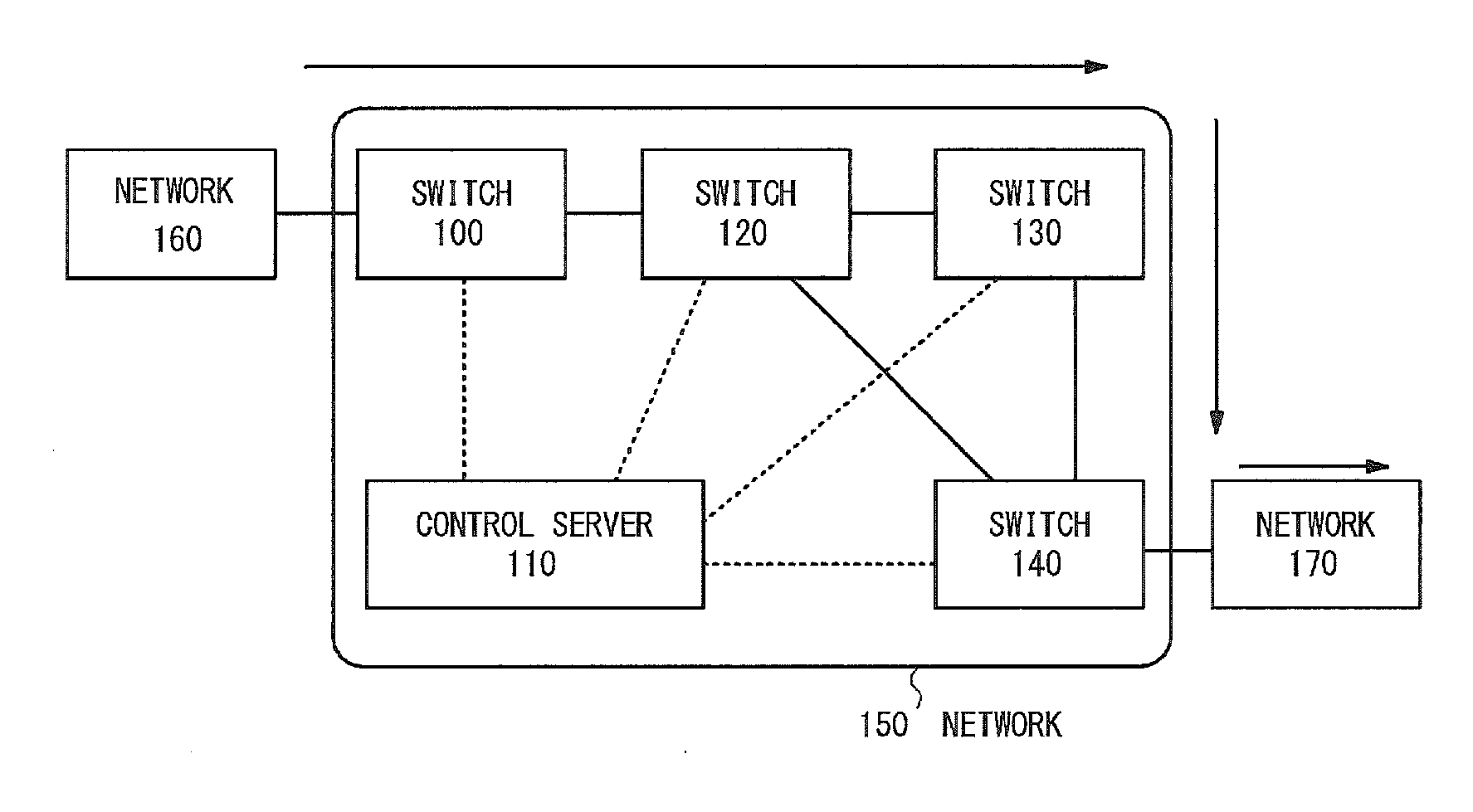
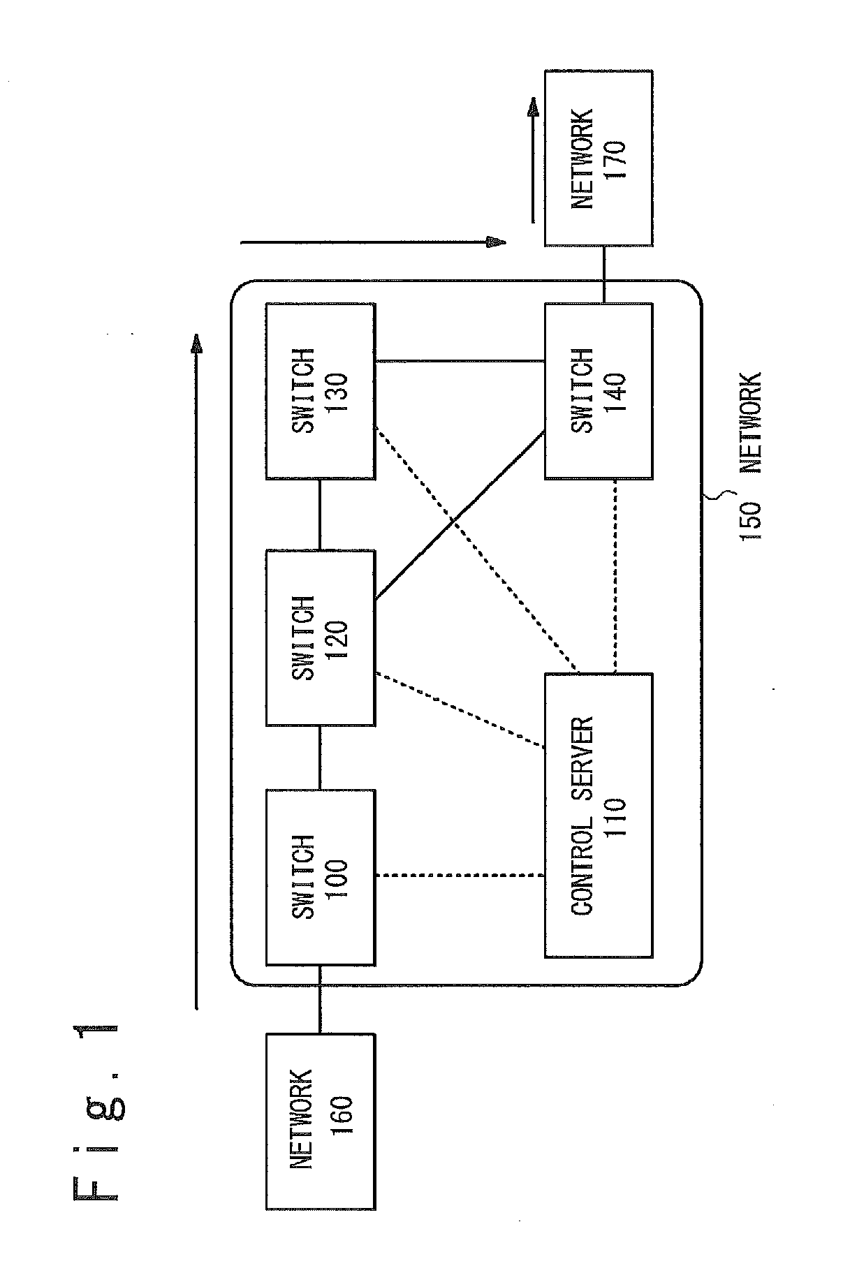
[0031]FIG. 1 is a block diagram showing a configuration of a system according to the first exemplary embodiment. The system shown in FIG. 1 includes a network 150, a network 160, and a network 170. The network 150 includes a switch 100, a switch 120, a switch 130, a switch 140, and a control server 110. An operation of the network 150 will mainly be described below. Arrows in FIG. 1 show a route of a packet (the switch 100-the switch 120-the switch 130-the switch 140) which will be described in the exemplary embodiment. The control server 110 and the switches are connected as shown by dotted lines. The connection may be performed by the same network as the network connecting the switches or different dedicated lines.

[0032]Also, in the network 150, the switch 100 and the switch 140 respectively connected with the network 160 and ...

second exemplary embodiment

Configuration and Operation

[0096]A second exemplary embodiment of the present invention will be described below in detail with reference to FIG. 14. FIG. 14 is a block diagram showing a configuration of a system according to the present exemplary embodiment.

[0097]A system according to the present exemplary embodiment includes a switch 200 and a control server 210. The configuration of a network is the same as in FIG. 1, and the switches and the control server are replaced by those of FIG. 14.

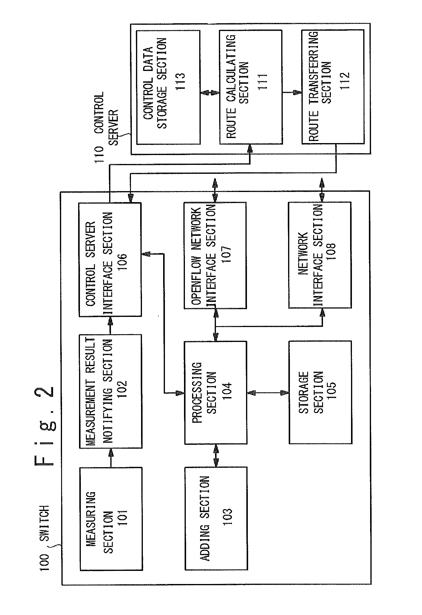
[0098]The switch 200 includes a measuring section 201, a measurement result notifying section 202, an adding section 203, a processing section 204, a storage section 205, a control server interface section 206, an OpenFlow network interface section 207, a network interface section 208, and an OAM section 209. The sections other than the OAM section 209 are the same as the sections of the switch 100 in the first exemplary embodiment shown in FIG. 2 and the description is omitted. The OAM section ...

third exemplary embodiment

Configuration and Operation

[0104]A third exemplary embodiment of the present invention will be described below in detail with reference to FIG. 15.

[0105]FIG. 15 is a block diagram showing a system configuration of the present exemplary embodiment. The system according to the present exemplary embodiment includes a communication unit 1000 and a control unit 1100. Though not shown in FIG. 15, the communication unit 1000 and the control unit 1100 belong to a network.

[0106]The communication unit 1000 includes a measuring section 1001, a measurement result notifying section 1002, an adding section 1003, and a processing section 1004.

[0107]The measuring section 1001 measures a communication state based on communication state measurement data when the communication unit 1000 is an entry edge node of the network.

[0108]The measurement result notifying section 1002 notifies the measurement result of the communication state to the control unit 1100 by the measuring section 1001, when the commu...


PUM


Abstract

A communication unit which belongs to a network is provided with an adding section, a measuring section, a measurement result notifying section, a processing rule storage section and a processing section. The adding section adds data for measurement of a communication state to a reception frame when the communication unit is the entrance edge node of the network. The measuring section measures the communication state based on the communication state measurement data when the communication unit is an exit edge node of the network. The measurement result notifying section notifies the measurement result to the control unit which controls the network. The processing rule storage section refers to identifier data of the reception frame and stores a processing rule relating the identification data of the reception frame and the processing of the reception frame. The processing section processes the reception frame based on the processing rule.

Description

TECHNICAL FIELD[0001]The present invention relates to a communication unit, a communication system, a communication method, and a recording medium which measure a state of a communication route.BACKGROUND ART[0002]In recent years, as a technique to perform route control on a communication network, a technique called “OpenFlow” is proposed in Non-Patent Literature 1. In the OpenFlow, communication is considered as an end-to-end flow, and route control, failure recovery, load balancing, and optimization are performed on a flow basis. An OpenFlow Switch (OFS) which functions as a transferring node, has a secure channel for communication with an OpenFlow Controller (OFC) and operates according to a flow table which is additionally written or a rewritten from the OFC. In the flow table, a set of a rule checked against a packet header, an action defining processing details, and flow statistic data is defined for each flow.[0003]For example, after receiving a packet, the OFS searches the f...

Claims


Application Information

Patent Timeline
Patent Type & Authority Applications(United States)
IPC IPC(8): H04L12/26H04L45/74H04L45/02H04L45/28
CPCH04L43/026H04L45/70H04L45/02H04L43/08H04L41/0659H04L43/50H04L41/40H04L43/20H04L45/54
Inventor SHIKITANI, NAOKI
Owner NEC CORP
Why Eureka
Try Eureka